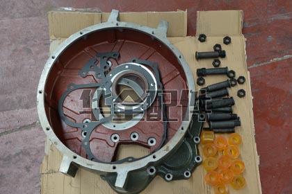
What is a generator flywheel and what is its function?
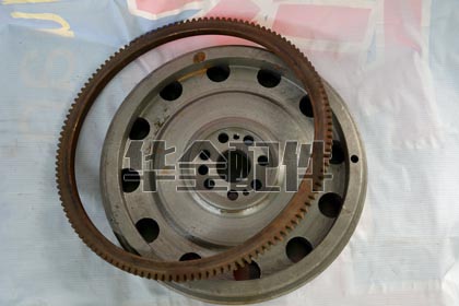
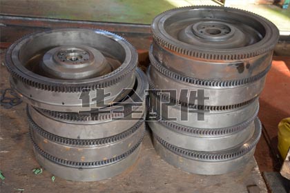
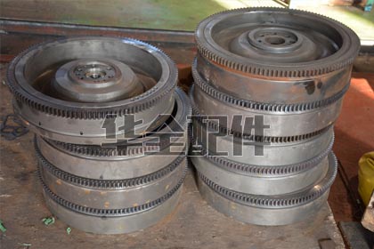
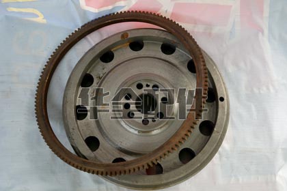
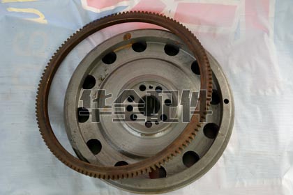
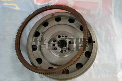
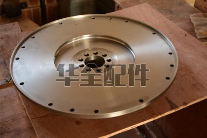
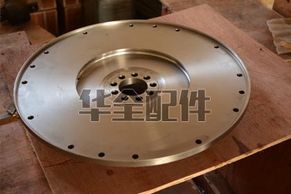
A generator flywheel is a heavy rotating disc bolted to the crankshaft rear flange that serves multiple critical functions: (1) Energy storage — its rotational inertia (typically 50-200 kg*m^2 for mid-size generators) smooths out the power pulses from individual cylinder firings, reducing crankshaft torsional vibration by 40-60% and ensuring steady rotational speed; (2) Starter ring gear carrier — the external ring gear (120-180 teeth) engages the starter motor pinion for engine cranking; (3) Coupling mounting surface — provides the precision-machined SAE flange and bolt pattern for connecting the generator alternator flexible coupling or clutch housing; (4) Timing reference — in many engines, the flywheel carries timing marks or a tone ring for the engine speed/position sensor. A flywheel weighs 30-200 kg depending on engine size — its mass is engineering necessity, not convenience.
What are SAE flywheel housing standards?
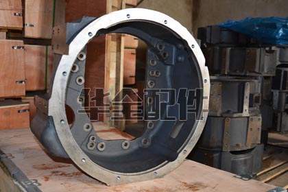
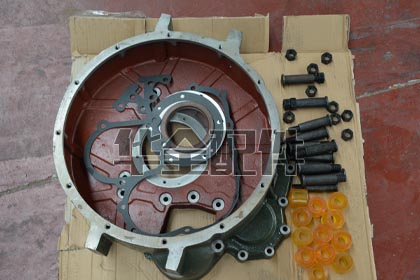
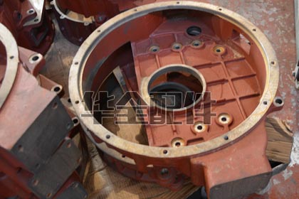
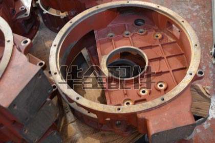
SAE (Society of Automotive Engineers) flywheel housing standards define interchangeable mounting dimensions for engine-to-transmission/alternator connections. Key SAE housing sizes: SAE 00 (largest, 787mm bolt circle, used on engines above 1,000kW), SAE 0 (648mm), SAE 1 (530mm, common for 200-600kW generators), SAE 2 (448mm), SAE 3 (410mm, common for 50-200kW), SAE 4 (362mm), SAE 5 (314mm), SAE 6 (216mm, smallest). Each SAE size specifies the housing flange bolt circle diameter, pilot bore diameter, number of bolts, bolt size, and face-to-crankshaft-flange depth. This standardization allows any SAE-compliant alternator to bolt to any SAE-compliant engine — fundamental to the generator packager industry.
What are the symptoms of a cracked or damaged flywheel?
Flywheel damage indicators: (1) Metallic knocking or rumbling from the bell housing area that changes with engine load — not RPM — indicating a loose flywheel or cracked hub; (2) Starter grinding noise — damaged ring gear teeth cause the starter pinion to skip, producing a metallic grinding sound; (3) Excessive crankshaft end play — measured at the front pulley with a dial indicator, beyond the 0.05-0.30mm specification; (4) Oil leak from the rear main seal area — a cracked or loose flywheel allows the crankshaft to oscillate, destroying the rear main seal; (5) Vibration at a specific RPM that passes through and disappears — the flywheel's natural frequency is being excited. Cracked flywheels are a critical safety risk — a flywheel separating at rated speed stores kinetic energy equivalent to a small car at highway speed.
Which engine brands are HUAQUAN flywheels and housings compatible with?
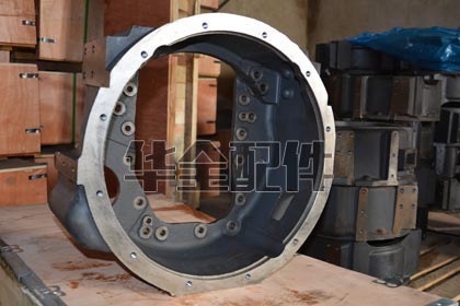
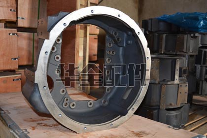
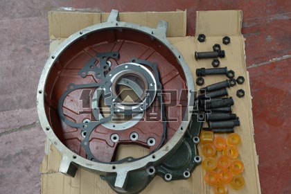
HUAQUAN supplies flywheels and SAE housings for: Cummins (4BT-6CT, ISB-ISL, NT855, KTA19/38/50, QSK), Perkins (1103-4008), Deutz (912-2015), Weichai (WD615/618, WP10/12/13/17, 226B, 6160-6200), Yuchai (YC4-YCK), Shangchai (SC4H-SC33W), and all Chinese diesel platforms. Flywheels are available in SAE 0 through SAE 6 with corresponding ring gear tooth counts. Each flywheel is dynamically balanced to ISO 1940 G6.3 and supplied with the correct mounting bolt set (Grade 12.9 minimum). Also available: flywheel housings in SAE sizes with rear main seal bore, starter mounting pad, and sensor ports.
What is a flywheel ring gear and when should it be replaced?
The ring gear is a hardened steel toothed ring (typically induction-hardened to 45-55 HRC) shrink-fitted onto the flywheel periphery. It engages the starter motor pinion gear during engine cranking. Replace when: (1) More than 2-3 consecutive teeth are chipped, broken, or severely worn — the starter pinion will skip on the damaged section; (2) Teeth are worn to a sharp 'knife-edge' profile rather than the original involute gear profile, causing starter pinion clash; (3) During any major engine overhaul — preventative replacement is inexpensive insurance. Replacement procedure: heat the ring gear uniformly to 200-250 degrees C (using an oven or induction heater — never a torch which creates hot spots), the thermal expansion allows the ring to slip off. Heat the new ring gear to the same temperature, drop it onto the flywheel (machined shoulder ensures axial positioning), and allow to air-cool for the shrink fit — the interference is 0.3-0.5mm on diameter.
How do I measure SAE flywheel housing size?
Measurement method: (1) Count the number of housing-to-block mounting bolts (SAE 6 = 8 bolts, SAE 5 = 8, SAE 4 = 8, SAE 3 = 12, SAE 2 = 12, SAE 1 = 12, SAE 0 = 16, SAE 00 = 16); (2) Measure the bolt circle diameter from opposite bolt centers — SAE 3 = 410mm, SAE 2 = 448mm, SAE 1 = 530mm; (3) Measure the pilot bore diameter — the precision register that centers the alternator housing. Most common generator sizes: 50-200kW = SAE 3 or 2; 200-600kW = SAE 1; 600-1,000kW = SAE 0; above 1,000kW = SAE 00. If the engine data plate is missing, measure and count — two of the three measurements (bolt circle, bolt count, pilot bore) will uniquely identify the SAE size.
What is the flywheel-to-alternator coupling and why is it critical?
The coupling connects the engine flywheel to the alternator rotor shaft, transmitting the full engine torque (typically 1,500-5,000 Nm for mid-size generators) while accommodating three types of misalignment: (1) Angular misalignment — the engine and alternator shaft axes are not perfectly parallel; (2) Parallel (radial) misalignment — the shafts are parallel but offset; (3) Axial displacement — thermal expansion changes the distance between the engine and alternator. The coupling provides torsional flexibility to dampen the power pulses from individual cylinder firings, protecting the alternator rotor from fatigue. Common types: flexible disc couplings (glass-fiber reinforced polymer discs, 0.25-0.5 degrees misalignment), rubber-in-compression couplings, and gear couplings (for high-torque applications). A failed coupling can destroy both the flywheel and the alternator rotor bearings.
What causes flywheel housing cracking?
Causes: (1) Misalignment — the number one cause. When the alternator is not perfectly aligned to the flywheel housing, the coupling generates a bending moment on the housing flange with each rotation, causing fatigue cracking at the bolt holes; (2) Loose housing bolts — a single loose bolt shifts the load to adjacent bolts, overstressing them and the housing material around them; (3) Overhung load — the alternator weight plus dynamic loads from vibration must be supported by the housing flange; exceeding the housing's rated bending moment causes cracking; (4) Impact damage — from improper lifting or transport; (5) Thermal stress — flywheel housings can reach 100+ degrees C; rapid cooling from water spray causes thermal shock cracking. Cracked housings are generally not repairable — the precision SAE register bore cannot be restored by welding.
What is the proper torque procedure for flywheel bolts?
Flywheel bolts are among the most critical fasteners on the engine: torque procedure: (1) Verify new bolts are being used — flywheel bolts on turbocharged engines are typically TTY (single-use); (2) Clean all threads on the crankshaft flange with a thread chaser — debris causes false torque readings; (3) Apply moly-based assembly lubricant to bolt threads and under-head surfaces — moly provides consistent friction coefficient (0.10-0.12) for accurate torque-to-clamp load conversion; (4) Install all bolts hand-tight; (5) Tighten in a cross-pattern to 50% of final torque; (6) Second pass to 100% of final torque; (7) For TTY bolts: apply specified angle rotation (typically 60 degrees + 60 degrees or 90 degrees + 90 degrees depending on the manufacturer); (8) Verify with a torque wrench after angle tightening — the breakaway torque should exceed the initial torque. Typical torque values: M12 (Grade 12.9) = 120-140 Nm, M14 = 180-210 Nm, M16 = 280-330 Nm.
How often should the flywheel and housing be inspected?
Inspection schedule: (1) Visual — at every oil change (250-500 hours): look for oil leaks at the rear main seal area indicating seal wear (not directly the flywheel but related); (2) Detailed inspection — at every major service (2,000-4,000 hours): inspect ring gear teeth through the starter mounting hole with a borescope, check all housing bolts with a torque wrench, verify the flywheel-to-housing runout with a dial indicator (maximum 0.25mm TIR); (3) Full inspection — at major overhaul (10,000-25,000 hours): remove the flywheel, magnetic particle inspect for cracks, measure ring gear tooth wear with a gear tooth vernier, replace the ring gear if teeth are worn beyond 20% of original thickness, re-balance the flywheel, replace all mounting bolts.
Can a dual-mass flywheel be used on a generator engine?
Dual-mass flywheels (DMF) — two flywheel masses connected by arc springs for torsional vibration damping — are common in automotive diesel applications but are generally NOT recommended for industrial generator engines. Reasons: (1) Generator engines operate at constant speed (1,500/1,800 RPM) where torsional vibration is a known, manageable frequency — the DMF's variable damping is unnecessary; (2) DMFs have a finite fatigue life of 200,000-400,000 km in automotive use — a generator accumulating 2,000 hours/year at 1,500 RPM experiences equivalent 'mileage' rapidly; (3) The stop-start nature of standby generators accelerates DMF spring fatigue; (4) A failed DMF is far more catastrophic than a failed solid flywheel. Industrial generators universally use solid flywheels with external torsional couplings at the alternator interface.