
Generator Sensors and Gauges — Complete Guide
Sensors and gauges are the generator’s nervous system — they continuously monitor critical engine parameters and provide the data that protects your generator from catastrophic failure. From basic mechanical gauges on portable units to sophisticated CAN-bus sensor networks on industrial generator sets, understanding sensor types, failure modes, and calibration requirements is essential for reliable generator operation. This guide covers all common generator sensors and gauges.
Essential Generator Sensors and Their Roles
| Sensor | Measurement | Sensor Type | Normal Range | Shutdown Threshold (Typical) |
|---|---|---|---|---|
| Oil Pressure Sensor | Engine oil pressure | Resistive (variable resistor), 4-20mA, or voltage output | 30-80 psi (2-5.5 bar) at rated speed, hot | <15 psi (1 bar) at rated speed |
| Coolant Temperature Sensor | Engine coolant temperature | NTC thermistor (resistance decreases with heat), RTD | 85-95°C (185-203°F) under load | >105°C (221°F) typically; some at 110°C |
| Speed / RPM Sensor | Crankshaft rotational speed | Magnetic pickup (VR – variable reluctance) or Hall effect | 1500 RPM (50 Hz) / 1800 RPM (60 Hz) | ±10-15% from rated RPM triggers overspeed/underspeed |
| Fuel Level Sensor | Fuel tank level | Float-type resistive, ultrasonic, or capacitive | 5-95% tank capacity | <10-15% triggers low fuel alarm |
| Battery Voltage Sensor | DC system voltage | Direct voltage measurement (controller internal) | 12.5-14.5V (12V system) / 25-28.5V (24V system) | <10.5V or >16V (12V); <21V or >32V (24V) |
| Exhaust Temperature (EGT) | Exhaust gas temperature at manifold or turbine inlet | K-type thermocouple | 350-550°C pre-turbo (diesel at rated load) | >650-700°C (engine-specific; check manual) |
| Intake Air Temperature | Temperature of air entering engine | NTC thermistor or semiconductor | 15-45°C ambient-dependent | Derating starts >40°C; typically no direct shutdown |
| Crankcase Pressure Sensor | Crankcase blow-by pressure | Differential pressure transducer | <5 mbar above atmospheric | >15-20 mbar indicates excessive blow-by |
Gauge Types — Analog vs. Digital
| Gauge Type | Advantages | Disadvantages | Best Application |
|---|---|---|---|
| Mechanical (Direct-Reading) | No power required; inherently reliable; instantaneous response; easily verifiable with known good gauge | Limited to pressure and temperature; capillary tube damage risk; no remote monitoring | Backup verification of electronic sensors; simple portable generators |
| Electric Analog (Needle Gauge) | Familiar analog display; quick visual scan of multiple gauges; can be panel-mounted | Accuracy ±5%; no data logging; sensor failure can show normal reading (pegged at zero or max) | Basic generator panels; cost-sensitive applications |
| Digital Display (LCD/LED Panel) | High precision (±1%); multi-parameter display; alarm setpoints; data logging | Harder to spot trends at a glance; backlight required in low light; more expensive | Modern generator controllers; critical monitoring applications |
Common Sensor Failure Modes
- Oil Pressure Sensor Drift: Mechanical diaphragm fatigue or electrical contact corrosion over time causes readings to drift. A sensor showing 10 psi when a mechanical gauge shows 35 psi is failed — do not trust the electrical reading without verifying.
- Magnetic Pickup Gap Drift: Vibration causes the magnetic pickup to back out, increasing the gap. Signal amplitude drops below the controller’s detection threshold, causing “no speed signal” faults. Re-gap and locktite the threads.
- Coolant Temperature Sensor Open Circuit: Broken wire or corroded connector reads as infinite resistance, which appears as extreme cold to the controller. This prevents the controller from triggering a high-temperature alarm on most designs.
- Thermocouple Junction Failure: K-type thermocouples exposed to sustained high temperature eventually suffer from grain growth and oxidation at the junction, causing readings to drift low (under-reading actual temperature).
Frequently Asked Questions
1. How do I test a generator oil pressure sensor?
Disconnect the sensor connector. Measure sensor resistance (for resistive type) with a multimeter — compare to the manufacturer’s pressure-to-resistance chart. Better: tee-in a known-good mechanical gauge at the sensor port. Run the engine and compare readings. If the mechanical gauge shows normal pressure but the controller reads low, either the sensor is faulty or there is a wiring issue between sensor and controller.
2. Can I use any coolant temperature sensor as a replacement?
No. Temperature sensors have specific resistance curves (NTC thermistor beta values) and the controller is programmed for a specific curve. Installing a sensor with a different resistance curve causes incorrect temperature readings and potentially false shutdowns or failure to shut down on over-temperature. Always match the sensor part number or verify the resistance curve matches the original.
3. What causes false overspeed faults?
Most common cause: magnetic pickup signal interference. The magnetic pickup generates an AC voltage whose frequency is proportional to RPM. Electrical noise from the battery charger, alternator, or nearby high-current cables can couple onto the sensor wiring and create false frequency readings. Solutions: use shielded twisted-pair cable for speed sensor wiring, route sensor wiring away from high-current cables, and verify proper grounding of the shield (at controller end only).
4. How often should generator sensors be calibrated?
Critical sensors (oil pressure, coolant temperature, speed) should be verified annually during routine maintenance. Compare each sensor against a known-good reference (mechanical gauge for pressure, IR thermometer for temperature, handheld tachometer for RPM). Most modern sensors cannot be field-calibrated — if they deviate beyond acceptable tolerance, replace them. Document verification results for trend analysis.
5. Why does my fuel level gauge show inaccurate readings?
Fuel level sensor inaccuracy is usually caused by: (1) float arm bent or stuck, (2) resistive track in the sender worn (causes dead spots), (3) poor ground connection at the tank sender (most common cause of erratic readings), (4) tank not level, or (5) sender not calibrated for the tank depth. Start diagnostics at the sender ground connection — this fixes the majority of fuel gauge problems.
6. Can I add sensors to an older generator that wasn’t equipped with them?
Yes, if the controller has spare analog or digital input channels. Many aftermarket controllers (DSE, ComAp, Datakom) have configurable auxiliary inputs that can accept additional sensors (4-20mA, 0-10V, or resistive). Common additions include: exhaust temperature monitoring, fuel level with remote tank, vibration sensor, and ambient temperature. Check your controller’s I/O expansion capability before purchasing sensors.
Related Articles
- Generator Sensors and Probes — Detailed Technical Guide
- Generator Controller Parts Overview
- Digital Generator Control Panels
- Generator Troubleshooting Guide
- Generator Engine Parts — Systems Overview
- Generator Fuel System Parts
- Complete Generator Maintenance Guide
Product Gallery
Cummins
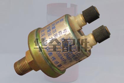
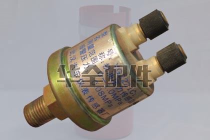
Various
Weichai
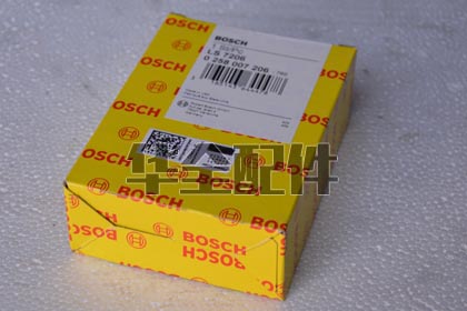
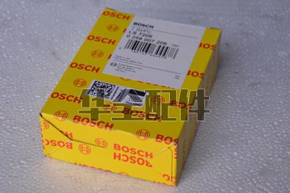
FAQ
Q: What sensors are essential for generator monitoring and protection?
A: Essential generator sensors: (1) Coolant Temperature Sensor — thermistor or RTD type, monitors engine temp and triggers high-temp alarm at 95-105 degrees C and shutdown at 105-110 degrees C; (2) Oil Pressure Sensor — pressure transducer or switch, alarms at 15-20 PSI below normal and shutdown at 5-10 PSI to prevent bearing seizure; (3) Speed/Frequency Sensor — magnetic pickup (MPU) counting flywheel ring gear teeth, provides RPM signal to the governor and controller; (4) Oil Temperature Sensor — critical for large engines to detect bearing distress early; (5) Fuel Level Sensor — float, ultrasonic, or capacitive type in the day tank; (6) Coolant Level Sensor — prevents overheating from coolant loss; (7) Battery Voltage Sensor — monitors charging system health; (8) Exhaust Gas Temperature (EGT) sensor — thermocouple type, detects over-fueling or post-turbo issues. All sensors should be compatible with the generator controller’s input types: 4-20mA analog, 0-5V, resistive (thermistor), or digital (CAN bus J1939).
Q: How do I calibrate a generator temperature sensor?
A: Calibration method depends on sensor type: For thermistor (NTC/PTC) sensors — measure resistance at known temperatures using a calibrated thermometer in a temperature-controlled bath. Compare against the sensor’s resistance-temperature curve from the datasheet. At 25 degrees C, a typical NTC coolant sensor reads 2,000-3,000 ohms. If the reading deviates more than 5%, replace the sensor — thermistors cannot be adjusted. For RTD (PT100) sensors — measure resistance at 0 degrees C (ice water bath, should read 100.0 ohms) and 100 degrees C (boiling water, should read 138.5 ohms). For thermocouples — use a thermocouple calibrator to simulate known temperatures and adjust the controller’s cold junction compensation. Never calibrate a sensor while still mounted on a running engine — the vibration and heat will produce inconsistent readings.
Q: Which generator brands use compatible sensors from HUAQUAN?
A: HUAQUAN supplies replacement sensors compatible with: Cummins (4BT-6CT through QSK95 — temperature, pressure, speed sensors equivalent to Cummins OEM 3408xxx, 3865xxx, 4921xxx series), Perkins (1100-4000 series), Deutz (912-2015 series), Volvo Penta (TAD/TWD series — 2079xxxx sensors), MTU/Detroit Diesel, Weichai (WP4-WP13 series, WD615/WD618), Yuchai (YC4-YC6 series), Shangchai (SC4-SC13 series), Weifang engines (all R-series platforms). Our sensors are cross-referenced to VDO, Datcon, Stewart Warner, Murphy, Beede, and Faria gauge-sender combinations. We supply both the sensor/sender unit AND the matching gauge as calibrated pairs to ensure accuracy.
Q: What causes false readings on generator gauges?
A: False gauge readings are caused by: (1) Poor ground connection — the most common cause; the sensor, gauge, and battery must share a common ground with less than 0.1 ohm resistance between them. Run a dedicated ground wire from the gauge panel to the engine block; (2) Corroded sensor connector terminals — oxidation creates a series resistance that shifts readings; (3) Wrong sensor-gauge pairing — a European VDO 10-180 ohm sensor connected to a US Stewart Warner 240-33 ohm gauge will show dramatically wrong values; (4) Voltage drop in the gauge power supply — gauge readings drift if the supply voltage varies (install a regulated 12V/24V instrument supply); (5) Electromagnetic interference from the alternator charging system — route sensor wiring away from AC alternator output cables; (6) Coolant sensor reading air instead of liquid — caused by low coolant level, air pockets after coolant change, or sensor mounted at a high point in the system.
Q: What is a magnetic pickup (MPU) sensor and how do I set the proper gap?
A: A magnetic pickup (MPU) is a passive electromagnetic sensor that generates an AC voltage pulse each time a flywheel ring gear tooth passes its tip. The output frequency is directly proportional to engine RPM (frequency Hz = RPM x teeth / 60). Standard ring gears have 118-184 teeth. Proper installation: (1) Thread the MPU into the flywheel housing port until it touches a ring gear tooth; (2) Back it out 3/4 to 1 full turn — this creates a 0.5-0.75mm (0.020-0.030 inch) air gap; (3) Lock the jam nut; (4) Crank the engine and verify AC voltage output at the controller — minimum 2.0V AC during cranking (100-150 RPM) is required for reliable speed detection. Output increases with RPM — typically 5-15V AC at rated speed. Use twisted-pair shielded cable for the MPU wiring, grounding the shield only at the controller end. Never route MPU cable in the same conduit as power cables.
Q: How do I troubleshoot a non-functional oil pressure gauge?
A: Troubleshooting steps: (1) Verify the engine actually has oil pressure — install a mechanical test gauge in the oil gallery port to confirm; (2) With the key ON and engine OFF: a variable-resistance sender should show some resistance (typically 240 ohms at zero pressure, decreasing to 33 ohms at full scale for US-standard gauges); (3) Ground the sender wire momentarily — the gauge should swing to full scale (maximum reading). If it doesn’t, the gauge or wiring is at fault; (4) With the sender wire disconnected: gauge should read zero or below zero. If it reads full scale, the sender wire is shorted to ground; (5) Check sender resistance changes with engine running — resistance should decrease as pressure increases; (6) Measure voltage at the gauge power terminal — should be within 0.5V of battery voltage. Common failures: sender internal diaphragm rupture (oil enters the electrical section), pressure port clogged with sludge, gauge internal voltage regulator failure.
Q: What is the difference between a sensor, sender, switch, and transducer?
A: Sensor — general term for any device that detects a physical condition. Sender — a resistive sensor designed to drive an analog gauge (e.g., a variable-resistance temperature sender that changes resistance with temperature to deflect a gauge needle). Switch — a binary on/off device that changes state at a preset threshold (e.g., a 105 degrees C temperature switch that closes a contact to trigger a shutdown relay). Transducer — a sensor that converts a physical measurement into a standardized electrical signal, typically 4-20mA or 0-5VDC, for input to an electronic controller. Modern generators use a mix: switches for critical shutdowns (low oil pressure, high coolant temp) provide fail-safe operation even if the controller fails; transducers provide continuous monitoring and data logging. HUAQUAN supplies all four types with proper thread sizes (1/8 NPT, 1/4 NPT, 3/8 NPT, M10x1.0, M12x1.5, M14x1.5, M16x1.5).
Q: How often should generator sensors be replaced?
A: Sensor replacement intervals: (1) Oil pressure and coolant temperature switches/senders — every 8,000-10,000 running hours or 5-7 years. These are the most critical protection devices; preventive replacement during a major service is recommended over waiting for failure; (2) Magnetic pickup (MPU) — inspect annually for metal debris accumulation on the magnetic tip; replace every 12,000-15,000 hours or if the AC output during cranking drops below 2.0V; (3) Exhaust gas temperature thermocouples — replace every 8,000-10,000 hours; they drift due to metallurgical changes at sustained high temperatures; (4) Fuel level senders — 10+ years in clean diesel, 5-7 years with biodiesel above B5 due to corrosion; (5) Coolant level sensors — 5-7 years regardless of hours; electrode-type sensors build up mineral deposits that cause false readings. Document all sensor part numbers and calibration values in the generator maintenance log.
Q: Why does my generator temperature gauge fluctuate during operation?
A: Causes of gauge fluctuation: (1) Air pockets in the cooling system passing over the sensor — bleed the cooling system thoroughly, especially the high points; (2) Intermittent electrical connection — check for loose or corroded spade connectors at the sender, gauge, and inline connectors. A wiggle test while reading the gauge can identify the problem connection; (3) Thermostat cycling — normal behavior if fluctuation is 5-10 degrees C around the thermostat opening temperature (82-95 degrees C); the thermostat opens and closes to regulate temperature; (4) Voltage regulator failure in the instrument cluster — if all gauges fluctuate together; (5) Ground loop — the engine and control panel may have different ground potentials. Add a dedicated ground strap between the engine block and the gauge panel; (6) EMI from a failing alternator diode — check for AC ripple on the DC system; over 0.5V AC indicates a failed diode causing gauge interference.
Q: Can I use automotive sensors on my industrial generator?
A: Not recommended. Automotive sensors operate in the -40 to +125 degrees C ambient range with moderate vibration levels. Industrial generator sensors are designed for continuous duty in 50-80 degrees C engine room environments with sustained high-frequency vibration that causes automotive sensor connector fretting and internal wire fatigue. Key differences: (1) Generator sensors use sealed MIL-spec or Deutsch connectors, not exposed spade terminals; (2) Vibration rating: industrial sensors are tested to 20G continuous, automotive typically 5-10G; (3) Chemical resistance: generator sensors resist diesel fuel, oil, coolant, and cleaning solvents; (4) Accuracy: industrial pressure transducers are typically 0.5-1% full scale vs 2-3% for automotive; (5) Output stability over temperature: industrial sensors specify drift in % per degrees C, automotive sensors typically don’t. Using an automotive oil pressure switch that fails at 3,000 hours on a prime power generator running 8,000 hours/year means unprotected operation within months.
Q: What is J1939 CAN bus and how do sensors communicate over it?
A: SAE J1939 is the standard CAN bus protocol for diesel engines, operating at 250 kbit/s over a twisted-pair shielded cable. On J1939-equipped engines, sensors connect to the Engine Control Module (ECM), not directly to gauges. The ECM broadcasts sensor data as Parameter Group Numbers (PGNs) on the CAN bus: Coolant Temperature (PGN 65262), Oil Pressure (PGN 65263), Engine Speed (PGN 61444), Fuel Rate (PGN 65266), and dozens more. The generator controller reads these PGNs and displays values, eliminating the need for individual sensor wiring to the control panel. J1939 provides: (1) Reduced wiring — 3 wires (CAN-H, CAN-L, shield) replaces 20+ individual sensor wires; (2) Richer data — the ECM provides derived values (fuel consumption, load percentage, DTC fault codes) that individual sensors cannot; (3) Built-in diagnostics — sensor fault codes identify exactly which sensor failed and the failure mode. The CAN bus must be terminated with 120-ohm resistors at both ends.
Q: How do I add additional monitoring sensors to an existing generator?
A: Adding sensors requires checking the controller’s available input channels. Most modern controllers (Deep Sea, ComAp, Smartgen) have spare analog inputs configurable for 4-20mA, 0-5V, or resistive. Procedure: (1) Identify unused analog inputs in the controller configuration software; (2) Select a sensor with the correct output type matching the input; (3) Wire the sensor with shielded cable, grounding the shield at the controller end only; (4) Configure the input in the controller software — set the sensor type, curve (linear or custom lookup table), units, alarm thresholds, and shutdown thresholds; (5) Test with a signal simulator before connecting the physical sensor; (6) Label all new wiring clearly. Common additions: exhaust gas temperature (predictive turbo/injector health), fuel consumption (operational cost tracking), coolant pressure (pump health), and intake manifold temperature (intercooler performance).
Q: What is the difference between analog gauges and digital displays for generators?
A: Analog gauges (needle-type) provide instant visual recognition — a quick glance tells you if the needle is in the ‘green zone’ without reading a number. They are immune to software glitches and continue displaying even if the controller reboots. Digital displays provide precise numeric values, multi-parameter display on a single screen, data logging, and alarm setpoints. Best practice for critical generators: use both — analog gauges for oil pressure and coolant temperature as independent backup (they work even with complete controller failure), and a digital controller for comprehensive monitoring and protection. Many marine classification societies (ABS, DNV, Lloyd’s) require independent analog gauges for critical parameters regardless of digital system presence.
Q: Why is my fuel level gauge reading incorrectly?
A: Fuel level gauge inaccuracy stems from: (1) Sender float arm bent during installation — calibrate by bending the arm so the float reaches both the full and empty positions; (2) Wrong sender resistance range — US standard is 240-33 ohms (empty-full), European standard is 10-180 ohms (empty-full). Mixing these gives reversed or nonsensical readings; (3) Sender not matched to tank depth — a sender with 200mm travel in a 500mm deep tank only reads the top 40%; (4) Fuel sloshing during operation — install a stilling well around the sender or use an ultrasonic non-contact sensor; (5) Corrosion on the sender’s resistive track — common with biodiesel or water-contaminated fuel, causing erratic jumping; (6) Float saturated with fuel — foam floats absorb diesel over time, altering buoyancy and causing consistently low readings. Ultrasonic and capacitive tank sensors eliminate the mechanical float issues and provide 0.5% accuracy.
Q: What should I check when commissioning new generator sensors?
A: Commissioning checklist: (1) Verify the part number against the engine serial number — sensor specifications can change within the same engine model year; (2) Confirm thread size and type — NPT (tapered), BSP (parallel with sealing washer), or metric straight thread with O-ring. Cross-threading a sensor into an expensive engine casting is a costly error; (3) Apply the correct thread sealant — liquid PTFE paste for NPT, copper crush washer for BSP, new O-ring for metric; never use Teflon tape which can shred and clog oil galleries; (4) Torque to specification — typically 15-25 Nm for 1/8 NPT sensors, 25-35 Nm for 1/4 NPT; (5) Perform a resistance check before connecting to the controller — verify the sensor output matches expected values at ambient conditions; (6) After engine start, verify the reading is plausible (oil pressure building within 3-5 seconds, coolant temperature rising gradually); (7) Test alarm and shutdown setpoints by simulating sensor faults (disconnection, short to ground) — confirm the controller responds correctly.