
Generator Voltage Regulators (AVR) — Complete Guide
The Automatic Voltage Regulator (AVR) is the component that maintains the generator’s output voltage within acceptable limits regardless of load changes. It does this by controlling the excitation current to the alternator’s field winding. A malfunctioning AVR causes voltage fluctuations that can damage connected equipment, trip protection devices, and in severe cases, cause generator shutdown. This guide covers AVR types, operation, diagnostics, and replacement.
AVR Types and Characteristics
| AVR Type | Excitation Power Source | Voltage Regulation | Response Time | Typical Application |
|---|---|---|---|---|
| Self-Excited (Shunt) | Residual magnetism in rotor + output voltage feedback through AVR | ±1-2% | 0.2-0.5 seconds | Small generators (5-50 kVA); simple, cost-effective; may fail to build voltage without residual magnetism |
| PMG (Permanent Magnet Generator) | Dedicated PMG exciter on rotor shaft; independent of output voltage | ±0.5-1% | 0.05-0.1 seconds | Medium-large generators (50-3000+ kVA); sustains short-circuit current; immune to output distortion |
| Auxiliary Winding (ARE) | Separate stator winding provides excitation power; partially independent of output | ±1-2% | 0.1-0.3 seconds | Mid-range generators (20-200 kVA); better short-circuit performance than self-excited |
| Digital AVR | Any excitation source; microprocessor-controlled with programmable parameters | ±0.25-0.5% | Programmable; 0.01-0.1 seconds | Modern generators all sizes; remote monitoring; paralleling-capable; soft recovery from transients |
AVR Troubleshooting Guide
| Symptom | Possible Cause | Diagnostic Step |
|---|---|---|
| No voltage output (generator runs but no voltage) | Lost residual magnetism; AVR failure; blown diode; open field winding | Test field winding resistance (should be 5-50Ω typical); measure residual voltage at AVR input (should be 5-12V AC); try field flashing |
| Voltage too high (overvoltage) | AVR sensing circuit fault; voltage sensing fuse blown; AVR failure | Check sensing fuse; verify AVR sensing leads are connected to correct voltage; measure AVR output to field — should decrease when output is high |
| Voltage too low (undervoltage) | Engine speed low; AVR setting drifted; field diode failure; AVR failure | Check engine RPM first (frequency = voltage before AVR); adjust AVR voltage potentiometer; test diodes |
| Voltage fluctuates (hunting) | AVR stability setting incorrect; engine governor hunting (affects frequency = affects AVR sensing); loose connection; failing diode | Adjust AVR stability potentiometer (small increments); verify engine RPM is stable first; check all connections |
| Voltage collapses under load | Undersized generator; AVR unable to drive sufficient field current; poor power factor load; blown rotating diode | Measure field current during load application; test rotating diodes; verify generator rating vs. actual load including starting surges |
Frequently Asked Questions
1. What causes an AVR to fail?
AVR failure causes include: (1) power surges or lightning strikes on the output, (2) sustained overload causing thermal stress, (3) moisture and dust contamination in the terminal box, (4) vibration-induced component or solder joint failure, (5) overvoltage from engine overspeed (AVR driving field beyond its rated current), (6) accidental short-circuit of field connections during maintenance, and (7) simple age — electrolytic capacitors dry out over 10-15 years.
2. Can I replace my AVR with a different brand?
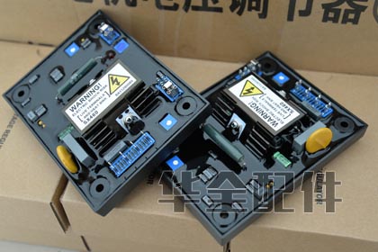
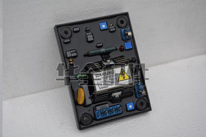
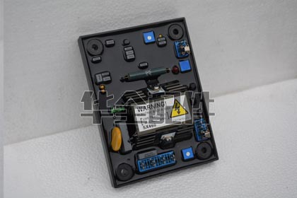
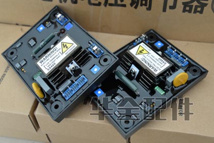
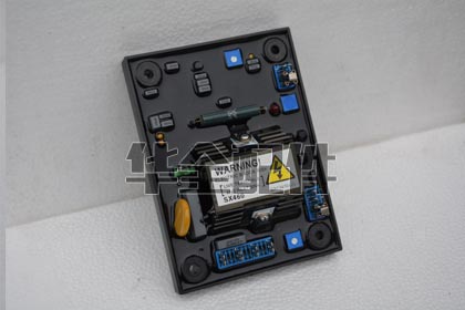
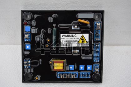
Yes, universal AVRs from manufacturers like SX440 (Stamford), AS440, EA440, MX341, and similar are widely compatible. Key specifications to match: excitation voltage range (typically 30-100V DC for smaller, 60-180V for larger machines), excitation current capacity (2-7A continuous typical), sensing voltage (120V, 240V, or 480V), and frequency setting (50/60 Hz). Many universal AVRs have DIP switches or jumpers for these settings.
3. How do I “flash” a generator that won’t build voltage?
Field flashing restores residual magnetism in the rotor. Method 1 (with engine stopped): disconnect AVR field leads, touch a 12V battery across the field leads for 3-5 seconds (positive to F+, negative to F-), then reconnect AVR. Method 2 (with engine running): use a “field flash” button if the AVR has one. Method 3: momentarily bypass the AVR and apply DC to the field through a current-limiting resistor. If flashing restores voltage but it’s lost on next restart, the rotor has lost its magnetic retention — replace the rotor or install a permanent field flash circuit.
4. Why does my generator voltage drop when I turn on a motor?
Motor starting draws 5-7 times the running current, causing an instantaneous voltage dip before the AVR and engine governor can respond. This is normal within limits. Acceptable voltage dip is typically 15-20% for general applications, 5-10% for sensitive electronics. If the dip is excessive: (1) check that the AVR’s stability and response settings are optimized, (2) verify the generator is adequately sized for motor starting, and (3) for PMG-excited sets, the dip should be minimal — if not, check the AVR.
5. Should I adjust my AVR’s voltage setting for different loads?
No. The AVR’s purpose is to automatically maintain voltage — manual adjustment should not be necessary for different loads. Set the voltage once (typically 120/240V for single-phase, 208/480V for three-phase) and leave it. If you find yourself needing to adjust frequently, there is an underlying problem: the AVR may be failing, there may be loose connections, the engine governor may not be maintaining speed, or load changes may be exceeding the generator’s capacity.
6. What is Under-Frequency Roll-Off (UFRO) on an AVR?
UFRO is a protective feature that reduces generator voltage proportionally when engine speed drops below a set threshold (typically 46 Hz for 50 Hz systems, 56 Hz for 60 Hz). This protects both the generator and connected equipment: motors draw excessive current at low frequency/voltage, and the AVR would otherwise try to compensate for low frequency by increasing excitation, potentially overheating the field. UFRO prevents these overloads. The voltage reduction is typically 1-3% per Hz below the threshold.
Related Articles
- Generator Controller Parts
- Digital Generator Control Panels
- Generator Alternators Guide (placeholder)
- Generator Sensors and Gauges
- Generator Troubleshooting Guide
- Generator Engine Parts — Systems Overview
- Complete Generator Maintenance Guide
Product Gallery
Cummins
Various
Weifang
1. What is a voltage regulator (AVR) and how does it work?
An Automatic Voltage Regulator (AVR) is an electronic device that maintains the generator’s output voltage within a narrow band (typically +/- 0.5-1%) regardless of load changes, engine speed variations, or temperature changes. Operating principle: (1) The AVR senses the generator’s output voltage (typically 190-240V AC for a 220/230V system, or 380-480V for a 440V system) through sensing leads; (2) It compares this sensed voltage to an internal reference voltage; (3) If the output voltage is too low, the AVR increases the DC excitation current to the alternator’s exciter field, strengthening the rotor magnetic field and raising the output voltage; (4) If the voltage is too high, the AVR decreases excitation current; (5) This closed-loop feedback control operates continuously in real-time — correction occurs within milliseconds. Key AVR features: voltage adjustment potentiometer, stability (damping) adjustment, under-frequency roll-off (U/FRO — reduces voltage when engine speed drops to prevent overheating), and external voltage adjust (remote potentiometer input). More advanced AVRs add: soft-start (voltage ramp), over-excitation protection, and VAR/PF control.
2. What is the difference between analog and digital AVRs?
Analog AVR — uses operational amplifiers, potentiometers, and analog components to perform voltage regulation. Advantages: Simple, proven, field-repairable by component replacement, low cost, easily understood by technicians. Disadvantages: Fixed parameters (no digital tuning), component drift over time, no communication capability, no data logging. Digital AVR — uses a microprocessor (DSP) with software-based control algorithms. Advantages: (1) Programmable parameters — gain, stability, voltage setpoint, U/FRO curve, soft-start ramp, all tunable via software; (2) Communication — Modbus, CAN bus, or USB for integration with generator controllers and SCADA; (3) Data logging — records voltage, current, excitation, and fault events; (4) Self-diagnostics — detects and reports: loss of sensing, over-excitation, under-frequency, short-circuit; (5) True RMS sensing — accurate even with distorted (non-sinusoidal) waveforms from non-linear loads. Disadvantages: Higher cost, requires programming knowledge, software-dependent. For new installations in critical applications (hospitals, data centers), digital AVRs are recommended. For simple standby generators with linear loads (lighting, basic motors), analog AVRs remain cost-effective.
3. How do I test an AVR before replacing it?
AVR diagnostic procedure (detailed in Alternators FAQ #13 above; key test): (1) Check input sensing voltage at AVR terminals — correct voltage present?; (2) Check AVR power input (separate from sensing on some AVRs); (3) Disconnect AVR from exciter field, use 12V battery to flash F+/F- — if generator builds voltage, the alternator and diodes are good, AVR is bad; (4) If battery flash doesn’t build voltage, test exciter winding resistance and rotating diodes before condemning AVR; (5) Check the external voltage adjust potentiometer — a failed remote pot (open circuit) can prevent the AVR from regulating. Bypass the remote pot by jumpering the relevant AVR terminals and using the onboard trim pot to test; (6) Inspect the AVR visually — burnt resistors, swollen capacitors, cracked solder joints, or a brown/black arc mark or burnt smell; (7) NEVER replace an AVR without checking the rotating diodes and surge suppressor first — a shorted diode will destroy the new AVR within seconds of startup. The diode test with a multimeter takes 5 minutes; replacing a second blown AVR takes $200-800 and a week of downtime.
4. What is a bridge rectifier and what role does it play in the excitation system?
A bridge rectifier converts the AC output of the exciter armature (rotating) into the DC current needed for the main rotor field. On brushless alternators, the bridge rectifier (6 diodes in a 3-phase full-wave configuration) is mounted on the rotor and rotates with it. The 3-phase AC from the exciter flows through the rectifier, becoming DC that feeds the main rotor. Without a functioning rectifier, the main rotor has no magnetic field and the alternator produces zero output voltage. Bridge rectifier testing: (1) Access the diode plate on the rotor (remove alternator end cover); (2) Using a multimeter in diode test mode, measure each of the 6 diodes individually. Forward bias should show 0.4-0.7V, reverse bias = OL (open); (3) A shorted diode (0V in both directions) shunts excitation current to ground, causing: no output voltage, AVR overloading and failure, or voltage collapse under load; (4) An open diode (OL both directions) reduces the excitation to half-wave on one phase, causing: lower maximum voltage, voltage instability under load; (5) Also test the surge suppressor (varistor/MOV across the DC output) — should read open. A shorted suppressor discharges the field; (6) When replacing: use exact replacements (same voltage and current rating), apply thermal grease to the diode base, and torque to specification.
5. What is the surge suppressor / varistor in the excitation system?
The surge suppressor (Metal Oxide Varistor / MOV) is a protective device connected across the DC excitation field (F+ and F-). Its function: absorbs high-voltage spikes that would otherwise damage the rotating diodes and the AVR. These spikes occur during: (1) Load rejection — when a large load is suddenly removed from the generator, the collapsing magnetic field induces a brief high-voltage spike; (2) Short circuits — a fault on the load side collapses the output voltage but the AVR is still trying to drive the field; (3) AVR failure — a failed AVR can send uncontrolled voltage to the field. The varistor has high resistance at normal operating voltage (20-100V DC for the exciter field) but instantly becomes low resistance (conductive) when the voltage exceeds its clamping threshold (typically 150-300V DC). This shunts the surge energy to ground, protecting the diodes. Testing: the varistor should read OPEN (infinite resistance) with a standard multimeter. A shorted varistor (zero ohms) will prevent the AVR from building voltage. If the varistor has failed (visible crack, burn mark, or measuring shorted), it MUST be replaced. Never operate a generator without the surge suppressor — a single load-rejection event can destroy a full set of rotating diodes.
6. Why does my generator voltage drop when I apply a heavy load?
Voltage sag under load: (1) Normal AVR response — the AVR should restore voltage to the setpoint within 1-2 seconds. A brief dip of 5-10% is acceptable; (2) Excessive sag (15%+) that doesn’t recover — check engine speed. If the engine also droops (frequency drops), the governor is the problem. The AVR reduces voltage proportionally (U/FRO function) to match the reduced speed, protecting the generator from over-fluxing. Fix the engine governor first; (3) Voltage sags and stays low even though frequency is stable — the AVR cannot supply enough excitation current, OR one of the following: (A) Rotating diodes partially failed (one diode open reduces excitation capacity by ~17%); (B) AVR output transistor/circuit has degraded — it can’t deliver full rated field current; (C) Exciter winding has a turn-to-turn short, reducing its output; (D) AVR sensing wire connection is loose or corroded — the AVR ‘sees’ a lower voltage than actual and doesn’t try to compensate. Check the voltage at the AVR sensing terminals vs the output terminals under load; (4) Voltage sags and then overshoots (hunts) — the AVR’s stability/damping setting is wrong. Adjust the stability potentiometer.
7. How do I adjust the AVR voltage and stability settings?
AVR adjustment procedure: (1) Voltage adjustment — with the generator running at rated speed and NO LOAD, locate the ‘Voltage’ trim potentiometer on the AVR. Adjust slowly with a small flathead screwdriver while watching a calibrated voltmeter on the generator output. Set to nominal voltage (e.g., 220V L-N or 400V L-L). Small adjustments — 1/8 turn at a time; (2) Stability (damping) adjustment — the most critical and often misadjusted setting. With the generator running at NO LOAD, turn the ‘Stability’ or ‘Damping’ pot fully counter-clockwise until the output voltage begins to oscillate (hunt). Then slowly turn clockwise until the oscillation JUST stops. This is the minimum stable setting. Turn an additional 1/8 to 1/4 turn clockwise for a safety margin; (3) Test with a load change — apply 50-100% load suddenly (load bank step). The voltage should dip briefly and recover within 1-2 seconds with no or minimal overshoot. If it hunts (oscillates), increase stability (clockwise). If it recovers too slowly (sluggish), decrease stability (counter-clockwise). The goal: fastest recovery without oscillation; (4) Under-frequency roll-off (U/FRO) — sets the frequency (engine speed) at which the AVR starts reducing voltage to protect the generator. Typically set to 46-47 Hz for 50 Hz systems, 56-57 Hz for 60 Hz. The voltage should begin decreasing 1-2 Hz below rated frequency. HUAQUAN provides AVR adjustment guides specific to each AVR model we supply.
8. What are the most common AVR failure modes?
AVR failure modes ranked by frequency: (1) Output transistor/MOSFET failure — the power semiconductor that controls excitation current fails short or open. Cause: overcurrent from a shorted rotating diode or exciter field winding, excessive ambient temperature, or lightning/surge events. This accounts for 60%+ of AVR failures; (2) Voltage sensing failure — the voltage sensing input (transformer, divider resistor) fails. The AVR either ‘sees’ zero voltage (over-excites, output voltage goes to maximum — dangerous) or ‘sees’ a fixed wrong voltage (regulates to the wrong setpoint). Typically caused by a loose or broken sensing wire, or a burnt resistor on the AVR board; (3) Power supply failure — the AVR’s internal power supply (derived from the generator output or a separate excitation winding) fails. The AVR has no power to operate. Cause: overvoltage, age-related capacitor failure, or diode failure in the rectifier circuit; (4) Remote potentiometer failure — external voltage adjust potentiometer fails (open circuit, usually from corrosion). The AVR reads infinite resistance and either shuts down or regulates to an incorrect voltage. Bypass the remote pot to test; (5) Fuse blown — many AVRs have a replaceable fuse. A blown fuse is a SYMPTOM — replacing it without finding the cause will result in another blown fuse. Check for shorted diodes and field winding; (6) Mechanical failure — vibration causes cracked solder joints, loose connectors, or broken potentiometers.
9. Can I use a universal AVR to replace an OEM AVR?
Yes, universal AVRs can replace many OEM AVRs, but COMPATIBILITY MUST BE VERIFIED. Key parameters to match: (1) Sensing voltage — most universal AVRs accept 190-240V AC (for 220V systems) or 380-480V AC (for 440V systems). Some accept both ranges via jumper or switch; (2) Excitation voltage/current output — the AVR must supply the voltage (typically 20-100V DC) and current (typically 2-10A DC) required by the alternator’s exciter field. Under-sizing the AVR causes voltage collapse under load. Over-sizing is fine; (3) Frequency — 50/60 Hz compatible. Most universal AVRs auto-detect or have a jumper; (4) Under-frequency roll-off (U/FRO) — must be suitable for your operating frequency. A 60 Hz AVR on a 50 Hz system will start rolling off the voltage at 57 Hz — well above the 50 Hz operating point, causing permanent low voltage; (5) PMG compatibility — if your alternator uses a PMG (Permanent Magnet Generator) for AVR power, the AVR must accept the PMG’s higher voltage (typically 150-250V AC) on its power input. Universal AVRs with a PMG power input option are available; (6) External voltage adjust potentiometer — match the pot resistance value (typically 1k, 2k, or 5k ohms). When replacing: (1) Take photos of the existing wiring; (2) Label all wires before disconnecting; (3) Wire the new AVR per its terminal diagram; (4) Set the voltage potentiometer to MINIMUM before starting; (5) Start and slowly adjust to rated voltage; (6) Adjust stability. HUAQUAN can cross-reference your OEM AVR to a suitable universal replacement.
10. What is under-frequency roll-off (U/FRO) and why is it important?
Under-Frequency Roll-Off (U/FRO), also called under-speed protection or V/Hz protection, is a critical AVR function that reduces the generator output voltage proportionally when engine speed (frequency) drops below a set threshold. Why it’s needed: the alternator’s magnetic core is designed for a specific volts-per-hertz (V/Hz) ratio. At the rated voltage and frequency (e.g., 400V at 50 Hz), the V/Hz ratio is 8 V/Hz. If the frequency drops (engine slows down) but the AVR maintains full voltage, the V/Hz ratio increases. Above approximately 1.1x rated V/Hz, the alternator’s magnetic core saturates. Saturation causes: (1) Excessive excitation current that overheats the exciter windings and AVR; (2) Distorted output waveform (peaked sine wave) that damages sensitive loads; (3) Excessive iron losses (eddy currents and hysteresis) in the stator core, causing overheating. U/FRO prevents all this by linearly reducing voltage as frequency drops below the ‘knee point’ (typically 46-47 Hz for 50 Hz, 56-57 Hz for 60 Hz). The generator delivers reduced but SAFE power at reduced speed, rather than full voltage that would cause damage. U/FRO is sometimes called the ‘Volts/Hz limiter’ in more advanced AVRs.
11. How do I wire a replacement AVR correctly?
AVR wiring guide: (1) TAKE PHOTOS of the existing wiring before disconnecting anything. Label each wire based on the terminal it connects to; (2) Power input wires (typically marked as ‘POWER’, ‘AUX’, or symbols ~ and ~) — these provide the AVR’s operating power and the excitation current source. Usually from the generator output (shunt-excited) or from a separate excitation winding. Two wires, AC, polarity doesn’t matter; (3) Sensing wires (typically marked as ‘SENSING’, ‘SENSE’, or ‘V-REF’) — the AVR monitors the generator output voltage through these. TWO wires, connect to generator output (phase-to-neutral for single-phase sensing, phase-to-phase for three-phase). POLARITY matters on some AVRs — follow the diagram; (4) Field output wires (F+ and F-) — these connect to the exciter field or brushes. F+ to positive brush/exciter terminal, F- to negative. POLARITY IS CRITICAL — reversing F+ and F- will prevent voltage buildup; (5) External voltage adjust (often marked ‘EXT VOLT ADJ’ or terminals for a 1k-5k ohm potentiometer) — connect a remote potentiometer or leave the terminals jumpered with the specified resistor value if not used; (6) Frequency selection jumper — most universal AVRs have a jumper or switch for 50/60 Hz. Set to match your generator BEFORE starting; (7) Ground/earth — connect to the generator frame for electrical noise immunity; (8) After wiring, DOUBLE-CHECK every connection against the diagram. A single miswire can destroy the AVR instantly; (9) Before starting, set the Voltage potentiometer to MINIMUM. Start the generator and slowly increase voltage to nominal while watching the voltmeter.
12. What is a PMG (Permanent Magnet Generator) and why do some alternators have it?
A PMG (Permanent Magnet Generator) is a small, independent permanent-magnet alternator mounted at the non-drive end of the main alternator rotor. It provides: (1) Independent AVR power — the AVR receives its operating power from the PMG, not from the generator output. This means: (A) Short-circuit current sustain — during a fault, the generator output voltage collapses, but the PMG (spinning with the rotor at full speed) continues providing full power to the AVR. The AVR can continue driving the exciter field at maximum, producing 3x rated current for up to 10 seconds to trip downstream breakers; (B) Immunity to non-linear loads — voltage waveform distortion from thyristor/VFD loads does not affect AVR power supply; (2) Faster voltage recovery — the PMG provides constant, clean power to the AVR independent of generator output, enabling faster response to load steps; (3) When is PMG needed: (A) Applications with high motor starting loads (direct-on-line motors 50%+ of generator rating); (B) Sites with significant non-linear loads (UPS, VFDs, rectifiers); (C) Paralleling applications where short-circuit coordination is critical; (D) Critical facilities (hospitals, data centers). Not needed for: simple standby generators with linear loads (lighting, heating, standard motors). A PMG can be retrofitted to many alternators — HUAQUAN supplies PMG retrofit kits for Stamford and Leroy-Somer alternators.
13. What causes generator voltage to fluctuate (flicker)?
Voltage fluctuation/flicker causes: (1) Engine speed hunting — the governor causes RPM to oscillate, and the AVR follows (or the U/FRO function interacts with the oscillation). The root cause is the governor, not the AVR. Fix the governor stability; (2) AVR stability setting too sensitive — the AVR is over-correcting. Increase the stability/damping setting; (3) Intermittent load — a load that cycles on/off rapidly (e.g., a compressor short-cycling due to a faulty pressure switch). Observe if the flicker coincides with a load change; (4) Loose or corroded connection in the AVR sensing circuit — the AVR ‘sees’ a fluctuating voltage due to the intermittent connection and tries to correct it. Check all sensing wire connections; (5) Rotating diode intermittent failure — a diode that is failing (not completely shorted or open, but intermittent) can cause fluctuating excitation; (6) Brushes (on brush-type alternators) — worn brushes making intermittent contact, or dirty slip rings. Clean slip rings with a commutator stone, replace brushes; (7) Non-linear load — thyristor/SCR controllers switching on and off at the line frequency cause voltage notching and waveform distortion. Some AVRs are more sensitive to this than others; (8) Capacitive load (long cable runs, power factor correction capacitors) — can cause the AVR to become unstable. Test by disconnecting the capacitive load. Diagnostic approach: record the flicker severity, frequency, and whether it correlates with load changes. A power quality analyzer recording will show whether the fluctuation is random (electrical noise), periodic (governor/AVR oscillation), or load-correlated.
14. What is the difference between a shunt, auxiliary-wound, and PMG excitation system?
Three excitation power sources for the AVR: (1) Shunt excitation (self-excited) — the AVR draws its power from the generator’s own output. Simplest and most common on small to medium generators (up to 500-1000kVA). Advantages: simple, low cost. Disadvantages: voltage collapses during short-circuit (no fault current sustain), sensitive to waveform distortion; (2) Auxiliary winding (AREP / series boost) — the stator has a separate excitation winding (in addition to the main output winding) that provides AVR power. The excitation winding is designed to maintain some output even when the main winding is loaded. Advantages: better short-circuit current than shunt (typically 2.5-3x rated for 10 seconds), moderate cost increase. Disadvantages: adds stator complexity; (3) PMG excitation — a separate permanent-magnet generator on the rotor provides independent AVR power. Advantages: maximum short-circuit current sustain (3x for 10 seconds), completely independent of output waveform, fastest response. Disadvantages: higher cost, adds length to the alternator. Selection guide: Shunt — acceptable for standby generators with linear loads, no motor starting. Auxiliary Wound — recommended for generators with moderate motor starting or some non-linear loads. PMG — required for critical applications with high motor starting, UPS loads, or paralleling. HUAQUAN can identify your alternator’s excitation type and supply the correct AVR.
15. How do I test a rotating rectifier (diode bridge) with a multimeter?
Rotating rectifier testing (detailed in Alternators FAQ #12 above; key steps): (1) Access the diode plate by removing the alternator end cover; (2) Disconnect the exciter rotor leads from the diode plate (photograph first); (3) Set multimeter to DIODE TEST mode; (4) Test each of the 6 diodes individually: Forward bias — red probe on anode (P-side of diode), black on cathode (threaded stud typically). Should read 0.4-0.7V. Reverse bias — swap probes. Should read OL (open). A shorted diode = 0V both directions; open diode = OL both directions; (5) Also test the surge suppressor (varistor/MOV) across the DC output — should read open circuit. A shorted suppressor prevents voltage buildup; (6) When replacing a diode: note the polarity (anode vs cathode stud), apply thermal compound to the mounting base, torque to specification (typically 25-35 Nm), and test resistance from the stud to the plate (should be OL if the diode is isolating correctly). A single shorted diode drains the exciter output — the generator may produce very low voltage or none.