
Generator Alternator Parts: Components, Maintenance and Replacement Guide
The alternator—also called the generator end or gen-end—is the component that converts mechanical energy from the engine into electrical power. While the engine gets most of the attention in maintenance discussions, alternator failures account for approximately 25% of generator breakdowns according to industry service data. Understanding alternator components, their failure modes, and maintenance requirements is essential for anyone responsible for backup power reliability.
Generator Alternator Components Overview
| Component | Function | Failure Mode | Typical Lifespan |
|---|---|---|---|
| Stator Windings | Stationary copper windings that produce output voltage | Insulation breakdown from heat/contamination | 20,000–40,000 hours |
| Rotor Assembly | Rotating magnetic field created by DC excitation | Bearing wear, winding shorts, imbalance | 15,000–30,000 hours |
| Exciter Stator | Provides initial excitation current to the rotor | Winding failure, diode failure | 10,000–20,000 hours |
| AVR (Voltage Regulator) | Controls excitation current to maintain stable output voltage | Component aging, surge damage, overheating | 8,000–15,000 hours |
| Rotating Rectifier | Converts AC exciter output to DC for the main rotor | Diode short or open circuit | 10,000–15,000 hours |
| Bearings | Support rotor shaft; allow smooth rotation | Wear, lubrication failure, contamination | 20,000–40,000 hours (regreased) |
| Cooling Fan | Air circulation for winding heat dissipation | Blade damage, loose mounting | Indefinite with inspection |
| Terminal Block | Connection point for output cables | Corrosion, overheating, loose connections | Indefinite with maintenance |
Alternator Maintenance Schedule
| Interval | Task | Tools Required |
|---|---|---|
| Weekly | Visual inspection for dust, moisture, corrosion; listen for bearing noise | Flashlight |
| Monthly | Check and record insulation resistance with megger; clean air filters | Megohmmeter (500V) |
| Quarterly | Torque-check all electrical connections; inspect brushes and slip rings | Torque wrench, inspection mirror |
| Semi-Annually | Clean internal windings with dry compressed air (max 30 psi); check bearing grease | Compressed air, grease gun |
| Annually | Full insulation resistance test; diode test on rotating rectifier; bearing replacement if indicated | Megger, multimeter, bearing puller |
Common Alternator Failure Modes and Diagnosis
1. Loss of Residual Magnetism
After extended storage or a severe short circuit, the rotor loses its residual magnetic field. The engine starts and runs normally, but no voltage builds up. This is the most common cause of “generator runs but no power” service calls. The fix is simple: flash the field by applying 12VDC (for most units) across the exciter field terminals for 2–3 seconds. If voltage builds and then collapses, the AVR—not residual magnetism—is the root cause.
2. Automatic Voltage Regulator (AVR) Failure
AVR failure manifests as unstable voltage, zero output, or voltage that doesn’t respond to load changes. Common causes include: voltage spikes from the utility during transfer, overheating from poor ventilation, component aging (electrolytic capacitors dry out), and moisture ingress. Always verify sensing voltage is reaching the AVR before condemning it—a broken sensing wire mimics AVR failure perfectly.
3. Rotating Rectifier Diode Failure
The rotating rectifier assembly contains 3–6 diodes that convert the exciter’s AC output to DC for the main rotor field. A single shorted diode can reduce output to zero. A single open diode causes voltage instability under load. Testing requires a multimeter in diode mode—each diode should show 0.4–0.7V forward bias and open circuit in reverse. Failed diodes are the second most common cause of “no output” after AVR issues.
4. Bearing Failure
Alternator bearings are typically sealed or regreasable deep-groove ball bearings. Warning signs include increasing noise (hum that becomes a grinding sound), elevated temperature at bearing housings, and visible grease leakage. Catastrophic bearing failure can cause the rotor to contact the stator, resulting in irreparable winding damage. Replace bearings at the manufacturer’s recommended interval regardless of apparent condition.
5. Winding Insulation Breakdown
Insulation degrades through thermal aging, contamination (dust, oil, moisture), and voltage stress. The industry standard is to test insulation resistance with a 500V megger—readings below 1 megohm require immediate attention, while readings below 0.5 megohm indicate the alternator is unsafe to operate. Regular insulation testing creates a trend line that predicts failure well before it occurs.
Alternator Part Selection Guide
| Part | When to Use OEM | When Aftermarket is Acceptable | Average Cost |
|---|---|---|---|
| AVR | Always for in-warranty units | Basler or equivalent for out-of-warranty | $500–$2,500 |
| Bearings | Always—counterfeit bearings are common | SKF/Timken from authorized distributors only | $50–$500 |
| Rotating Rectifier | Recommended for exact fitment | Acceptable if diode specs match exactly | $100–$600 |
| Stator/Rotor | Always—no viable aftermarket exists | Rewinding by certified shop only | $2,000–$15,000 |
| Terminal Block | Not necessary | Any industrial-grade terminal block matching specs | $20–$100 |
FAQ
How do I test if my generator alternator is producing power?
With the generator running at rated speed, measure voltage at the alternator output terminals. If zero, first check the main circuit breaker. Then measure residual voltage—a healthy alternator produces 2–12VAC even without excitation. Zero residual voltage indicates total loss of residual magnetism or a major winding fault. Normal residual voltage with no build-up points to the AVR or rotating rectifier.
What causes a generator alternator to lose residual magnetism?
Extended storage without operation, a severe short circuit on the output, or accidentally applying external voltage to the output terminals can demagnetize the rotor. Generators stored more than 6 months without running are especially susceptible. Prevention is simple: exercise the generator monthly under load to maintain the magnetic field.
How often should I test alternator insulation resistance?
Monthly for critical applications; quarterly for standby generators in normal environments. More frequent testing in humid or dusty conditions. Use a 500V insulation tester (megger) and record readings to establish a trend. A sudden drop in insulation resistance—even if still above 1 megohm—indicates developing contamination or moisture ingress that should be investigated.
Can a generator alternator be repaired, or do I need to replace it?
Most alternator failures can be repaired rather than requiring complete replacement. AVRs are plug-and-play replaceable. Rotating rectifier diodes are straightforward to replace. Bearings are routine maintenance items. Even stator and rotor winding failures can often be addressed by rewinding at a certified motor shop. Complete alternator replacement is typically only necessary when the frame is damaged, laminations are shorted, or the cost of repair exceeds 60% of replacement.
What are the signs of imminent alternator bearing failure?
Listen for changes in noise—a smooth hum that develops a rhythmic roughness or grinding sound. Check bearing housing temperature with an infrared thermometer after 30 minutes of operation; temperatures above 80°C (176°F) warrant investigation. Grease leakage from sealed bearings or excessive grease consumption in regreasable bearings are early warning signs.
Why does my generator voltage fluctuate under load?
Voltage fluctuation under load typically indicates an AVR that cannot respond quickly enough (failing capacitors), a governor issue causing RPM fluctuation (which directly affects voltage since voltage is proportional to speed), or loose/dirty slip rings causing intermittent excitation current. Diagnose by ruling out RPM fluctuation first with a frequency meter, then testing the AVR’s response.
Related Resources
- Speed Controllers — RPM stability fundamentals for clean power
- Sensors & Probes — Monitor alternator temperature and performance
- Digital Control Panels — Advanced alternator monitoring and diagnostics
- Generator Maintenance Guide — Complete maintenance schedules including alternator
- Generator Parts Buying Guide — How to source quality alternator components
- Generator Spare Parts FAQ — Alternator inventory recommendations
- Generator Troubleshooting Guide — Systematic “no output” diagnosis
Product Gallery
Cummins
Various
1. What is a generator alternator and how does it produce electricity?
A generator alternator (also called the generator end or main alternator) converts mechanical rotational energy from the engine into electrical power through electromagnetic induction. Key components: (1) Rotor — the rotating magnetic field, either a wound rotor (DC current through slip rings creates the magnetic field) or a permanent magnet rotor (smaller generators); (2) Stator — the stationary winding where voltage is induced. The rotor's magnetic field sweeps past the stator windings, inducing AC voltage; (3) Automatic Voltage Regulator (AVR) — controls the DC current to the rotor (exciter field) to maintain constant output voltage regardless of load changes; (4) Exciter — a small AC generator on the same shaft that provides DC power to the rotor after rectification (brushless design). The alternator's output frequency (Hz) is determined by engine speed (RPM) and the number of rotor poles: f = (RPM x poles) / 120. A 4-pole alternator at 1,500 RPM produces 50 Hz; at 1,800 RPM produces 60 Hz.
2. What are the common alternator brands HUAQUAN parts are compatible with?
HUAQUAN supplies alternator components compatible with: Stamford (S0-S9, PI/P7 ranges, HC/HCI series), Leroy-Somer (LSA series, TAL series), Marathon (MagnaPLUS, MagnaMAX), Mecc Alte (ECO, ECP series), Engga, Faraday, WEG, Siemens, and Chinese brands (Wuxi, Fuan, KEPU, Starlight). Components include: automatic voltage regulators (AVRs), bridge rectifiers, rotating diode assemblies, surge suppressors/varistors, carbon brushes and brush holders, slip rings, bearing sets (drive end and non-drive end), exciter stators and rotors, main stator and rotor rewinding services, terminal blocks, and complete alternator replacement units. Each component is manufactured to meet the original alternator's insulation class (typically Class H, rated for 180 degrees C temperature rise) and voltage regulation specifications (+/- 0.5% to +/- 1% depending on AVR type).
3. What is an AVR and how do I know if mine is faulty?
The Automatic Voltage Regulator (AVR) is the electronic control board that maintains the generator's output voltage within specification by regulating the DC excitation current to the alternator rotor. Symptoms of AVR failure: (1) Output voltage too high or too low — the AVR has lost regulation. Measure voltage at no load and full load — a healthy AVR maintains voltage within +/- 1%; (2) Voltage hunting/fluctuating — the AVR's feedback loop is unstable, causing the voltage to oscillate 5-15V. Often caused by a failing potentiometer or capacitor; (3) No output voltage at all — the generator runs but produces no power. The AVR may be dead, but first check: loss of residual magnetism (try flashing the field), exciter diodes, and excitation breaker/fuse; (4) Voltage collapse under load — voltage drops 20%+ when load is applied. The AVR can't supply enough excitation current. Check the AVR's voltage sensing input — if it's sensing incorrectly (wrong voltage reference), it under-excites; (5) Burnt smell or visible damage on the AVR board — capacitor swelling, burnt resistors, or blown traces. Before replacing the AVR, check the rotating diodes and surge suppressor — a shorted diode can overload and destroy the new AVR within seconds.
4. How do I flash the generator field to restore residual magnetism?
Flashing the field restores the small amount of residual magnetism in the rotor core that is needed to initiate voltage buildup during startup. Procedure (BRUSHLESS alternators): (1) Stop the generator and disconnect the AVR from the exciter field wires (F+ and F-). Safety: lock out the start circuit; (2) Connect a 12V battery: positive to F+, negative to F-, for 3-5 seconds ONLY. Longer can overheat the exciter field winding. The polarity must be correct — reversing polarity can demagnetize instead of magnetize; (3) Disconnect the battery, reconnect the AVR, and start the generator; (4) If voltage still doesn't build up: use 24V (two 12V batteries in series) for 2-3 seconds. NEVER exceed 24V on a 12V exciter field or use AC power; (5) For alternators with separate excitation terminals (X+/X- on Stamford), follow the manufacturer's specific procedure; (6) If flashing doesn't work: the issue is not residual magnetism — troubleshoot the AVR, rotating diodes, exciter windings, or main stator; (7) NEVER flash the field while the generator is running — the AVR is connected and the induced voltage can feed back into the battery, causing explosion or equipment damage. Residual magnetism loss is most common after long storage periods (6+ months).
5. What maintenance does a generator alternator require?
Alternator maintenance schedule: Monthly — visual inspection for dust/debris on windings (conductive dust causes tracking and flashover). Check for signs of overheating (discolored insulation, burnt smell). Verify vent screens are clean — blocked screens cause 20-30 degrees C higher internal temperature. Quarterly — measure insulation resistance (IR test / Megger test) of stator and rotor windings to ground. Minimum acceptable: 1 megohm per kV of rated voltage + 1 megohm (e.g., 480V alternator = 1.48 megohms minimum). Trending is more important than absolute value — a sudden drop from 500 to 10 megohms indicates moisture ingress or insulation degradation. Semi-annually — check and tighten all electrical connections (torque to specification — loose connections cause heating and fire). Inspect vibration isolators/mounts. Annually — clean windings with dry compressed air (MAX 30 PSI, COOL air — hot air can damage insulation). If windings are oily/greasy, use an approved electrical solvent cleaner and allow to dry completely before running. Replace bearings every 20,000-30,000 hours or when vibration increases. Check bearing grease condition — regrease if needed (follow manufacturer's grease type and quantity specification — over-greasing is as damaging as under-greasing).
6. What causes voltage fluctuations and how do I fix them?
Voltage fluctuation causes: (1) Engine speed instability — the governor is hunting (RPM oscillating). Since frequency and voltage are directly related to RPM, speed hunting causes voltage hunting. Fix the governor issue before touching the AVR; (2) AVR instability — the AVR's stability/damping potentiometer needs adjustment. Turn the 'Stability' or 'Damping' trim pot slowly clockwise until the voltage stabilizes, then test with load changes; (3) Loose or corroded voltage sensing connections — the AVR's feedback signal is degraded. Clean and tighten all sensing wires from the alternator output terminals to the AVR; (4) Load-side issues — non-linear loads (UPS, VFDs, welding equipment) introduce harmonics that confuse the AVR's RMS sensing. Consider an AVR with true RMS sensing or a line reactor; (5) Intermittent short in the exciter or main windings — a turn-to-turn short that makes and breaks with thermal expansion. IR test when cold and hot — a large difference suggests this; (6) Fluctuating engine speed due to fuel quality issues (water in fuel, clogged filter). The AVR is chasing the changing frequency. Always distinguish between 'voltage following speed' (the AVR is working correctly but input speed is unstable) vs 'voltage unstable at steady speed' (AVR problem).
7. What are carbon brushes and when should they be replaced?
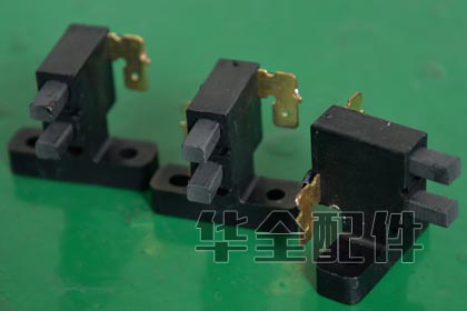
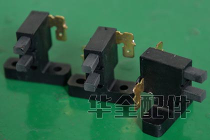
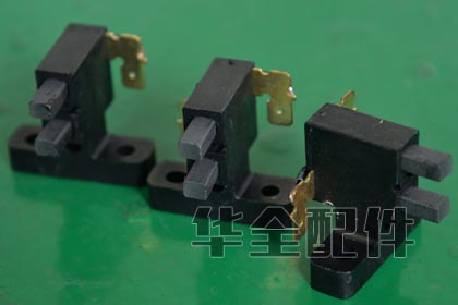
Carbon brushes are conductive blocks that transfer DC excitation current from the stationary AVR to the rotating field via slip rings (not used in brushless alternators — brushless designs use a rotating exciter and diodes). In brushed alternators, brush maintenance is critical: (1) Inspect brush length — replace when worn to 1/3 of original length (typically replace at 10-15mm remaining from about 30mm new). Running brushes too short causes spring tension loss, arcing, and slip ring damage; (2) Check brush spring tension — should be firm and even. Weak springs cause intermittent contact, arcing, and voltage hunting; (3) Inspect slip rings — should be smooth, shiny, and free of grooves. A grooved slip ring chews up new brushes rapidly and creates carbon dust. Lightly polish with fine crocus cloth (never emery cloth — conductive particles embed in the copper); (4) Brush seating — new brushes must be 'seated' to match the slip ring curvature. Run the alternator at no load for 1-2 hours to bed new brushes; (5) Carbon dust accumulation — conductive carbon dust can cause tracking and flashover between slip rings. Clean with dry compressed air and a vacuum (never use solvents that leave residue); (6) Uneven brush wear indicates the brush holder is misaligned or the spring tension is uneven — correct the alignment before replacing brushes. HUAQUAN supplies brush sets and complete brush holder assemblies for Stamford, Leroy-Somer, Marathon, and other major brands.
8. What is insulation resistance testing (Megger test) and why is it important?
Insulation Resistance (IR) testing applies a high DC voltage (typically 500V or 1,000V) between the winding conductors and ground (the alternator frame) and measures the leakage current. The result is expressed in megohms (MΩ). The test: (1) Detects moisture ingress — a wet winding may show 1-5 MΩ vs a dry winding showing 500+ MΩ; (2) Detects insulation aging and contamination — oil, dust, and carbon tracking degrade IR; (3) The Polarization Index (PI) is the ratio of the 10-minute IR reading to the 1-minute reading. A PI > 2.0 indicates healthy, dry insulation. PI < 1.5 indicates contamination or moisture. PI < 1.0 is critical — do not energize; (4) Minimum acceptable values: IR (1 min) should be at least (rated kV + 1) megohms. A 480V alternator: (0.48 + 1) = 1.48 MΩ minimum. However, this is an absolute minimum — trending is more important; (5) Always record IR values in the maintenance log with ambient temperature and humidity (IR drops ~50% for every 10 degrees C rise). A consistent downward trend means insulation is degrading; (6) If IR is low: for moisture, run the alternator unloaded with space heaters on (if equipped) to dry the windings. For contamination, clean with approved electrical solvent and dry thoroughly. For permanent insulation degradation, rewinding or replacement is indicated.
9. What are rotating diodes and how do I test them?
Rotating diodes (in brushless alternators) are mounted on the rotor shaft and convert the AC output of the exciter armature to DC for the main rotor field. They rotate with the shaft — hence 'rotating' diodes. Typical configuration: 6 diodes in a 3-phase full-wave bridge (3 positive, 3 negative). Testing procedure: (1) Disconnect the AVR and all external connections to the exciter stator; (2) Access the diode plate (remove the alternator end cover). Identify the diode plate assembly; (3) Using a digital multimeter in diode test mode: forward bias (positive lead on anode, negative on cathode) should show 0.4-0.7V drop. Reverse bias should show OL (open). Each diode must be tested individually — disconnect one lead to isolate the diode from the circuit; (4) A shorted diode (0V in both directions) will overload and destroy the AVR — NEVER replace an AVR without checking the diodes first. An open diode (OL both directions) reduces excitation capacity, causing voltage collapse under load; (5) Also test the surge suppressor/varistor across the field — it should show open circuit. A shorted varistor discharges the field instantly, causing voltage collapse; (6) When replacing diodes: use the exact replacement part with the correct voltage and current rating. Tighten to the specified torque — loose diodes overheat. Apply thermal grease between the diode base and the heat sink. HUAQUAN supplies complete diode plate assemblies and individual diodes for Stamford, Leroy-Somer, and Marathon alternators.
10. How do I test the generator alternator stator and rotor windings?
Stator testing (engine off, all leads disconnected): (1) Continuity test — measure resistance between each pair of output leads (U-V, V-W, W-U for 3-phase). All three readings should be within 5% of each other and match the manufacturer's specification (typically 0.1-2 ohms for large alternators). A significant difference indicates a turn-to-turn short; (2) Ground test — measure resistance from each output lead to the alternator frame (ground). Should be infinite (OL on meter). Any reading below 1 MΩ indicates ground fault; (3) Visual inspection — look for discolored insulation (overheating), burnt spots (flashover), or mechanical damage. Rotor testing: (1) Measure resistance across the slip rings (F+ to F-). Should match specification (typically 5-50 ohms depending on alternator size); (2) Ground test — measure from each slip ring to the rotor shaft. Should be infinite; (3) For brushless alternators, the rotor winding is tested by measuring across the main rotor connections at the diode plate. Always discharge the winding after testing — the inductance stores a high-voltage kick that can shock you and damage your meter.
11. What causes a generator to produce low voltage or no voltage?
No/low voltage troubleshooting sequence: (1) Measure voltage at the generator output terminals (not at the transfer switch — eliminates cabling issues). Verify the voltmeter is working by testing a known live circuit; (2) Check the excitation circuit breaker/fuse — many generators have a small breaker or fuse protecting the AVR excitation supply. Reset/replace; (3) Check engine speed — at no load, the frequency should be 50 Hz (1,500 RPM) or 60 Hz (1,800 RPM). Low speed = low voltage AND low frequency; (4) Test residual magnetism — if the generator has been sitting for months, it may have lost residual magnetism. Flash the field; (5) Test AVR input voltage — the AVR needs a minimum sensing voltage (typically 5-10V AC) to begin regulating. If below this, the AVR won't function. On some AVRs, a separate excitation winding or PMG provides initial power; (6) Test AVR output — measure DC voltage at the AVR output terminals (F+ to F-) during startup. Should ramp up to 10-60V DC as the AVR tries to build voltage. Zero volts = dead AVR; (7) Test rotating diodes — a shorted diode shunts excitation current to ground; (8) Test main stator and rotor for opens or grounds; (9) For PMG (Permanent Magnet Generator) equipped alternators: test PMG output at rated speed — should be 150-250V AC. A failed PMG prevents AVR operation but the alternator can still be flashed manually as a diagnostic step.
12. What is a PMG (Permanent Magnet Generator) and do I need one?
A PMG is a small permanent magnet alternator mounted on the non-drive end of the main alternator shaft. It provides independent, isolated power to the AVR, completely separate from the main output windings. Advantages: (1) Short-circuit current sustain — during a fault, the main output voltage collapses, but the PMG maintains full AVR power, allowing the alternator to deliver 300% rated current for up to 10 seconds to clear downstream breakers. Without PMG, the AVR loses power during the fault and can't sustain short-circuit current; (2) Immunity to non-linear load distortion — the AVR's power supply is clean and stable regardless of how distorted the main output waveform is; (3) Better motor starting capability — the PMG provides full excitation during the voltage dip of a motor start, helping the generator recover faster. PMG is recommended (sometimes required) for: hospitals and healthcare (NFPA 110), data centers, any installation with large motor loads, and applications requiring high short-circuit current for selective coordination of downstream breakers. PMG is NOT necessary for: simple standby generators for lighting, small commercial backup, or residential use. HUAQUAN offers PMG-equipped alternators as an option on all generator sets.
13. How do I test a generator AVR before replacing it?
AVR testing and confirmation procedure: (1) Verify the AVR is receiving proper input — measure the sensing voltage at the AVR terminals (should be 190-240V AC for a 220V system, 380-480V for a 440V system). If the sensing voltage is correct but output is wrong, the AVR is suspect; (2) Test AVR power supply — the AVR gets its operating power from the generator output or a separate excitation winding. Measure the AVR power input terminals — should be within the AVR's specified range (typically 160-270V AC); (3) Disconnect the AVR from the exciter field and connect a 12V battery briefly to the field wires (F+ and F-). If the generator builds voltage (even 100-200V) when flashed, the alternator and diodes are functional — the AVR is the problem; (4) Test AVR output — reconnect the AVR with a DC voltmeter across its output (F+/F-). Start the generator. If the AVR outputs 0V DC regardless of speed, it's dead. If it outputs voltage but the main output is still wrong, the connection to the exciter field is broken; (5) Check the AVR's external potentiometer for voltage adjustment — these are common failure points. Bypass the remote pot by connecting the AVR's voltage adjust terminals directly and using the onboard trim pot; (6) Inspect the AVR for burnt components, swollen capacitors, or cracked solder joints. A visual inspection often reveals the failure; (7) Substitute with a known-good universal AVR (set to correct voltage/frequency) as a final test. If the problem persists with a new AVR, the fault is in the alternator itself.
14. What causes alternator bearing failure and how do I prevent it?
Alternator bearing failure causes: (1) Misalignment — the engine and alternator shafts must be aligned within 0.05mm (0.002 inch) both radially and angularly. Misalignment causes side-loading that destroys bearings in 500-2,000 hours. Always check alignment after moving a generator or replacing flexible couplings; (2) Over-greasing — more grease is NOT better. Excess grease churns in the bearing, causing overheating and grease breakdown. Follow the manufacturer's EXACT quantity: typically 5-10 grams per bearing for small alternators, 20-30 grams for larger ones; (3) Incompatible grease — mixing lithium-based and polyurea-based greases causes chemical breakdown. Stick to one type, clearly labeled; (4) Belt tension — on belt-driven alternators, excessive belt tension side-loads the drive-end bearing. Set tension to manufacturer specification; (5) Contamination — water, dust, or conductive debris entering the bearing. Verify that bearing seals are intact and the alternator's IP rating (typically IP23) is appropriate for the environment; (6) Electrical pitting (EDM) — on VFD-driven motors, stray currents can arc through bearings. Less common on generators but occurs on paralleled sets with ground current issues. Prevention: alignment check at installation and annually; vibration monitoring (ISO 10816 — bearing vibration velocity should be below 4.5mm/s RMS); thermography (bearing temperature should be below 80 degrees C); and ultrasonic inspection for early detection.
15. What are the options for upgrading an older generator alternator?
Alternator upgrade options: (1) Direct replacement — swap the existing alternator with a new unit of the same frame size, voltage, and mounting. Simplest option, plug-and-play. HUAQUAN stocks common frame sizes (UC224, UC274, PI144, S4, LSA46.2, etc.) for rapid replacement; (2) AVR upgrade — retain the existing alternator but install a modern digital AVR with true RMS sensing, soft-start, and communication capability. Improves voltage regulation from +/- 1.5% to +/- 0.25% and enables remote monitoring; (3) PMG retrofit — add a PMG (Permanent Magnet Generator) to an existing alternator that lacks one. Provides independent AVR power for short-circuit current sustain. Retrofittable on many Stamford and Leroy-Somer alternators with the PMG mounting provision; (4) Insulation upgrade — rewind the stator from Class B (130 degrees C) to Class H (180 degrees C) for higher ambient temperature operation or extended life; (5) Voltage change — rewind or reconnect the stator for a different voltage (e.g., 220V to 440V, or 50Hz to 60Hz). Requires also changing the AVR and potentially the engine governor setting; (6) Complete alternator replacement with a higher-efficiency model — modern alternators are 1-3% more efficient than 20-year-old units, paying back the investment in fuel savings over 3-5 years of prime power operation. HUAQUAN assesses your existing installation and recommends the most cost-effective upgrade path.