
Generator Clutch Parts — Complete Guide
While less common on stationary generator sets, clutches are essential components on PTO-driven (power take-off) generators, tractor-driven generator sets, and certain mobile power applications. A clutch allows the generator to be mechanically engaged and disengaged from the driving engine or power source. Understanding clutch components, wear patterns, and adjustment is critical for reliable operation of clutch-equipped generator systems.
Clutch Types for Generator Applications
| Clutch Type | Engagement Method | Torque Capacity | Typical Application | Maintenance Need |
|---|---|---|---|---|
| Dry Friction Plate Clutch | Mechanical linkage or hydraulic; spring pressure clamps friction disc to flywheel | 100-2000 Nm+ | PTO-driven generators; tractor generator sets; mobile power units | Adjust free play; inspect disc thickness; replace at minimum thickness |
| Multi-Plate Wet Clutch | Hydraulic or electromagnetic; multiple friction/steel plate stack in oil bath | 500-5000+ Nm | Heavy-duty industrial PTO; continuous slip applications; marine generators | Oil quality critical; clutch pack inspection at overhaul intervals |
| Centrifugal Clutch | Automatic; weights expand with RPM to engage | 5-200 Nm | Small engine-driven generators (5-20 kW); engages above set RPM automatically | Check shoe/pad thickness; verify engagement RPM; minimal routine maintenance |
| Electromagnetic Clutch | Electric current energizes coil creating magnetic field that clamps friction surfaces | 10-500 Nm | Automated start/stop systems; remote-controlled engagement; hybrid power systems | Check brush/slip ring condition; verify operating voltage and current; inspect friction surfaces |
| Overrunning / Sprag Clutch | Mechanical one-way; transmits torque in one direction, freewheels in reverse | Varies widely | Dual-drive systems; prevents back-driving of engine by generator | Inspect sprags for wear; one-way rotation test; typically very reliable |
Dry Clutch Components and Wear
| Component | Function | Wear Indicator | Replacement Criterion |
|---|---|---|---|
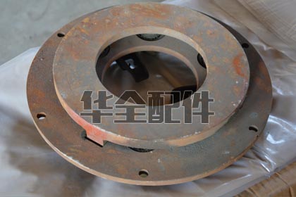
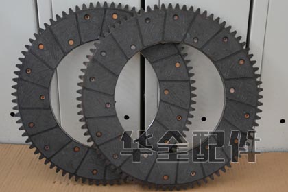
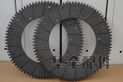
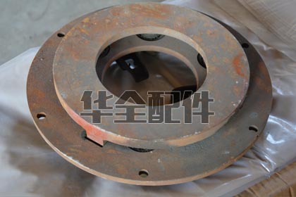
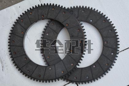
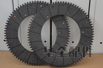
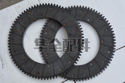
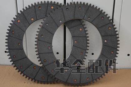
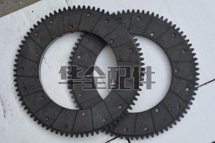
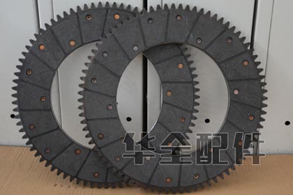
| Clutch Disc (Friction Plate) | Friction material bonded to steel plate; transmits torque when clamped between flywheel and pressure plate | Disc thickness measurement; rivet exposure | Replace when friction material thickness reaches minimum (typically 2-3mm above rivet heads) |
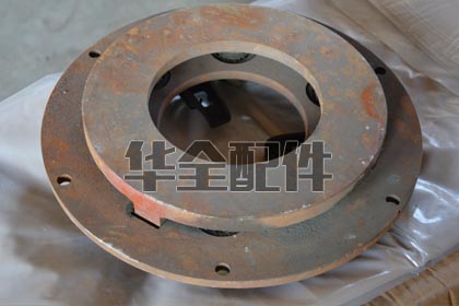
| Pressure Plate | Spring-loaded plate that clamps disc to flywheel; diaphragm or coil spring type | Scoring, heat checking, warpage | Replace if warped (>0.5mm runout), deeply scored, or heat-cracked |
| Release Bearing (Throwout Bearing) | Pushes against pressure plate diaphragm to release clutch; only loaded during disengagement | Noise when pedal depressed; roughness when rotated by hand | Replace at every clutch change regardless of apparent condition |
| Pilot Bearing / Bushing | Supports input shaft nose in flywheel or crankshaft; allows speed difference when clutch disengaged | Noise in neutral with clutch engaged (pedal up); input shaft wobble | Replace at every clutch change; inexpensive insurance against input shaft damage |
Frequently Asked Questions
1. Why does my generator clutch slip under load?
Clutch slip means the friction disc is not transmitting full engine torque to the generator. Causes in order of likelihood: (1) insufficient clutch free play — the release mechanism is partially disengaging the clutch even when the pedal is released (adjust free play to specification, typically 25-35mm at pedal), (2) worn clutch disc — friction material at or below minimum thickness, (3) oil or grease contamination on friction surfaces (rear main seal leak, over-greased pilot bearing), or (4) weak/damaged pressure plate springs. Address immediately — slip generates heat that destroys the clutch rapidly.
2. How do I adjust a mechanical clutch linkage?
Procedure: (1) Measure free play at the clutch pedal or lever — the distance it moves freely before resistance is felt. (2) Locate the adjustment point — typically a threaded rod and lock nut at the clutch release fork or cable adjuster. (3) Adjust to achieve manufacturer-specified free play (usually 25-40mm for pedal, 3-5mm at release bearing). (4) Verify the clutch fully engages (no slip under full load) and fully disengages (no gear grinding or drag). Lock the adjuster nut after adjustment.
3. Can I run my PTO generator with the clutch partially engaged?
Absolutely not. A partially engaged (slipping) clutch generates extreme heat at the friction surfaces — temperatures can exceed 500°C within seconds. This heat warps the pressure plate, glazes the friction material (permanent damage reducing friction), and can cause the flywheel to crack from thermal stress. The clutch must either be fully engaged (pedal released, no load on release bearing) or fully disengaged. There is no safe “partially engaged” operating mode.
4. How long should a generator PTO clutch last?
Properly operated and maintained, a dry clutch on a PTO generator should last 3,000-8,000 engagement cycles or 5,000-10,000 operating hours. Premature failure causes: (1) riding the clutch (operator rests foot on pedal), (2) excessive slip during engagement (engage decisively, not slowly), (3) overloading (clutch undersized for generator torque requirement), and (4) contamination (oil leaks onto friction surfaces). Generator clutches typically last longer than vehicle clutches because they see fewer engagement cycles.
5. Do I need a special clutch for a generator vs. a vehicle?
Generator clutches are often the same part as industrial/agricultural vehicle clutches if the engine and PTO are derived from that platform. However, generator service involves prolonged constant-speed, constant-load operation with few engagement cycles — different from vehicle service with frequent stops/starts. Key consideration: generator clutches must handle sustained torque at rated engine speed without overheating, and the engagement should be smooth to avoid generator voltage/frequency transients during coupling.
6. What maintenance does a generator clutch require?
Routine inspection includes: (1) check and adjust free play every 500 hours or quarterly, (2) inspect for oil leaks at rear main seal and transmission input seal — any leak becomes clutch contamination, (3) listen for release bearing noise during engagement/disengagement cycle, (4) verify full engagement by checking for slip at full load (listen/look for RPM difference between engine and generator), and (5) lubricate linkage pivot points per manufacturer schedule (avoid over-lubricating — excess grease can contaminate the clutch).
Related Articles
- Generator Engine Parts — Systems Overview
- Generator Lubrication System
- Diesel Engine Spare Parts for Generators
- Generator Engine Belts Guide
- Generator Troubleshooting Guide
- Complete Generator Maintenance Guide
- Generator Fuel System Parts
Product Gallery
Boling
Cummins
Various
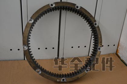
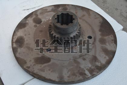
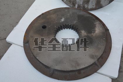
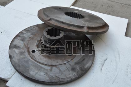
Weifang
1. What is a PTO clutch and how is it used with generators?
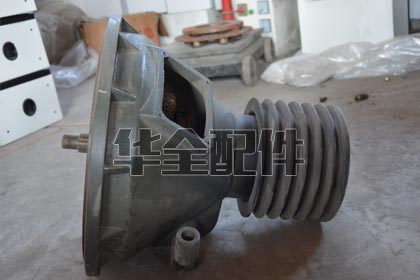
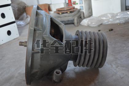
A Power Take-Off (PTO) clutch connects and disconnects the generator from its prime mover (typically a tractor, truck engine, or dedicated industrial engine). Unlike a standard generator where the engine is permanently coupled to the alternator, a PTO-driven generator allows the engine to be used for multiple purposes. The clutch: (1) Engages to transfer engine power to the generator when electricity is needed; (2) Disengages when the generator is not needed, allowing the engine to perform other work (tractor PTO for implements, truck engine for propulsion, pump drive). PTO clutches are commonly: mechanical (lever-actuated, friction disc), hydraulic (oil pressure-actuated multi-disc), or electromagnetic (electric coil-actuated). Typical applications: tractor-driven generators for farms, truck-mounted generator sets for mobile power, marine generators driven off the main engine PTO, and industrial co-generation where one engine drives both a generator and another machine (pump, compressor). HUAQUAN supplies clutch components including friction discs, pressure plates, release bearings, pilot bearings, and complete clutch assemblies.
2. How do I select the right clutch for a PTO generator application?
PTO clutch selection criteria: (1) Torque capacity — the clutch must handle the maximum continuous torque of the generator at full load. Torque (Nm) = (Generator kW x 9550) / RPM. Add a 20-30% safety factor for shock loads and transients; (2) Engagement type — mechanical (lever): lowest cost, simplest, operator must manually engage/disengage. Hydraulic: smoother engagement, remote control capable. Electromagnetic: instant engage/disengage, fully automated, requires electrical power; (3) PTO shaft speed — standard PTO speeds: 540 RPM and 1,000 RPM. The clutch must be rated for the operating speed. Note: a 1,000 RPM PTO clutch on a 540 RPM shaft has lower torque capacity — derate accordingly; (4) Duty cycle — how often and how long the clutch is engaged. Continuous engagement (generator running for hours) generates heat from friction — the clutch must be sized for thermal capacity, not just torque; (5) Alignment — the PTO shaft must be aligned within the coupling manufacturer’s specification. Misalignment destroys clutches; (6) Overload protection — a slip clutch or shear bolt in the PTO driveline protects both the clutch and the generator from sudden overloads. HUAQUAN application engineers can calculate the correct clutch specifications from your generator kW, RPM, and application details.
3. What are the signs of a worn or failing PTO clutch?
Clutch wear indicators: (1) Slipping — the engine RPM is correct but the generator output frequency is low or fluctuating. The clutch is slipping under load and cannot transmit full torque. Most noticeable when load increases; (2) Difficulty engaging — grinding or clashing when you try to engage. The clutch is dragging (not fully releasing) or the pilot bearing is seized; (3) Chatter/judder during engagement — the whole driveline shakes as the clutch engages. Caused by: worn or warped friction disc, oil/grease contamination on the disc, or broken damper springs in the clutch hub; (4) Noise when the clutch is disengaged (pedal up) — a squealing or growling that stops when you press the pedal. This is the release bearing — replace before it seizes and damages the pressure plate; (5) Noise when the clutch is engaged (pedal released) — a rumbling that changes with engine RPM. This is the pilot bearing (the bearing in the flywheel that supports the input shaft); (6) Cannot disengage — the clutch is stuck engaged. Causes: seized pilot bearing, broken clutch linkage, or warped friction disc that won’t release. This is dangerous — the generator cannot be stopped without shutting down the engine; (7) Burning smell — the friction material is overheating from slipping. Stop operation immediately.
4. How do I maintain a mechanical PTO clutch?
PTO clutch maintenance: Daily — check clutch engagement and disengagement before connecting to the generator. The PTO shaft should stop rotating within 2-3 seconds of disengagement (with no load). Weekly — inspect the clutch linkage (cable, rod, hydraulic line) for wear, fraying, or leaks. Check adjustment — excessive free play means the clutch isn’t fully engaging (slipping). Zero free play means the release bearing is constantly loaded (premature bearing failure). Typical free play: 1-2 inches at the pedal, or per manufacturer’s specification; Monthly — grease the release bearing (if greaseable — some are sealed). Grease the pilot bearing and clutch linkage pivot points. Wipe off excess grease — it can contaminate the friction disc; Annually — inspect the friction disc thickness through the inspection cover (if equipped). Minimum thickness is typically stamped on the disc hub. Replace when within 1-2mm of the rivet heads; Every 2,000 hours — consider replacing the clutch as preventive maintenance if it’s in a critical application. The cost of a clutch kit ($200-$800) is negligible compared to the downtime cost of a field failure. Always replace the complete clutch kit (disc, pressure plate, release bearing, pilot bearing) — replacing individual components leads to uneven wear and premature failure.
5. How do I troubleshoot a PTO generator that won’t maintain frequency under load?
Frequency sag under load — PTO-specific causes: (1) Clutch slipping — the most common PTO-specific cause. The engine maintains RPM but the generator frequency drops because the clutch can’t transmit the torque. Test: check if engine RPM (at the flywheel/PTO output) matches generator input RPM — a difference confirms clutch slip; (2) PTO shaft speed mismatch — the tractor/engine PTO is set to 540 RPM but the generator requires 1,000 RPM (or vice versa). The PTO speed selection lever was bumped to the wrong position; (3) PTO shaft universal joint angle too large — U-joints at extreme angles cause cyclic speed variation. The generator sees fluctuating RPM even though the engine’s average RPM is correct. Maximum U-joint angle: typically 15 degrees per joint, and the two joints should have equal angles; (4) PTO shaft too long/short — a shaft that bottomed out (too long for the compressed length) transmits thrust into the engine and generator bearings, causing drag. A shaft that’s too short can separate under load; (5) Tractor/prime mover engine governor not maintaining speed under load — the engine droops (RPM decreases with load increase). Adjust the governor droop to minimum (isochronous if the governor allows); (6) Generator AVR struggling with the speed fluctuation from the clutch slip — the AVR tries to compensate for the voltage drop but can’t fix the frequency drop. The solution is fixing the mechanical cause upstream, not adjusting the AVR.
6. What is a shear bolt / shear pin and why is it used on PTO generators?
A shear bolt (shear pin) is a sacrificial mechanical fuse in the PTO driveline designed to fail at a specific torque, protecting the more expensive components (clutch, gearbox, generator) from overload damage. If the generator rotor suddenly seizes (bearing failure) or the PTO shaft binds, the shear bolt breaks and decouples the driveline, absorbing the destructive energy. Shear bolt selection: the bolt is sized to shear at approximately 150-200% of the generator’s rated torque. Using a bolt that’s too strong defeats the protection — a standard hardware-store bolt may not shear until 5x rated torque, by which point the gearbox or generator is already destroyed. Always use the MANUFACTURER-SPECIFIED shear bolt — it has a precisely machined groove that controls the shear point. NEVER replace a shear bolt with a standard bolt — you’re removing the safety device. Keep spare shear bolts with the generator — replacement in the field takes 5 minutes vs days of downtime for a destroyed component. If a shear bolt fails, STOP and investigate WHY before installing a new bolt — a shear bolt failure is a symptom, not the root cause.
7. What are the options for remote engagement/disengagement of a PTO clutch?
Remote PTO clutch control options: (1) Cable-actuated — a push-pull control cable from the operator position to the clutch lever. Simple, reliable, inexpensive. Limited to about 5-8 meters cable length due to friction; (2) Hydraulic — a master cylinder at the operator position connected to a slave cylinder at the clutch. Smoother operation, longer distance capable (up to 20 meters). Requires periodic bleeding of air from the hydraulic fluid; (3) Pneumatic (air cylinder) — compressed air actuates the clutch. Fast engagement, high force. Requires on-site compressed air supply; (4) Electromagnetic clutch — the clutch itself is electrically engaged. A simple switch provides instant control from any distance. Most convenient for automated systems; (5) Electric over hydraulic — an electric pump provides hydraulic pressure to engage the clutch. Combines the convenience of electric control with the smoothness of hydraulic engagement. HUAQUAN can provide the complete control system (actuator, hoses/lines, control panel) integrated with the generator controller for automatic start/stop sequences.
8. How do I align a PTO shaft between the tractor and generator?
PTO shaft alignment: (1) Level the generator relative to the tractor — both should be on firm, level ground. Use the generator’s adjustable feet to match the tractor’s PTO output height; (2) Measure the horizontal and vertical offset between the tractor PTO stub shaft and the generator input shaft. The PTO shaft’s telescoping design accommodates some misalignment, but minimize it for longest universal joint life; (3) Set the PTO shaft length: with the shaft disconnected, measure the distance between the tractor PTO and generator input with the tractor and generator at their closest possible position. Cut the PTO shaft so it has at least 150mm (6 inches) of overlap in the telescoping section when at maximum extension, and at least 50mm (2 inches) of free travel when fully compressed. A shaft that’s too long bottoms out and destroys bearings. Too short and it can separate; (4) Phasing the universal joints: both U-joints must have their yokes in the SAME plane (aligned). If the yokes are 90 degrees out of phase, the shaft produces a pulsating output speed even with perfect alignment; (5) Install the safety shield — the plastic guard tube over the PTO shaft. This is NOT optional. A spinning PTO shaft without a guard is one of the most dangerous pieces of equipment on a farm — it will grab loose clothing and cause severe injury or death in less than one second.
9. Which generator applications benefit from a clutch vs direct coupling?
Clutch vs direct coupling decision guide: Use a clutch when: (1) The prime mover has multiple duties (tractor driving both PTO generator and farm implements); (2) The generator is used intermittently and you want to save fuel by disconnecting it; (3) You need to engage/disengage the generator under load — a direct-coupled generator always spins with the engine; (4) The installation requires a soft-start — the clutch can be slipped momentarily during engagement to gradually bring the generator up to speed, reducing shock loads. Use direct coupling when: (1) The engine is dedicated solely to the generator (standard genset configuration); (2) The generator runs continuously for long periods — a clutch engaged for thousands of hours is an unnecessary point of failure; (3) Maximum reliability is required — a direct coupling (flex disc or coupling spider) has no wearing parts; (4) Space is limited — a clutch adds length to the driveline. For mobile generator applications (truck-mounted, trailer-mounted), a PTO with clutch is standard. For stationary power plants, direct coupling is standard.
10. How does clutch engagement order matter with generator load?
Start-up and shutdown sequence for PTO generators: (1) Start the prime mover (tractor/engine) with the clutch DISENGAGED and the PTO in NEUTRAL. The engine starts with minimum load; (2) Let the engine warm up to operating temperature; (3) Bring the engine to the PTO’s rated speed (540 or 1,000 RPM typically); (4) Engage the PTO clutch SMOOTHLY. A slow, controlled engagement brings the generator up to speed gradually. ‘Dumping’ the clutch (fast engagement) sends a shock load through the entire driveline and can break shear bolts or damage gears; (5) Once the generator reaches rated speed (check frequency reading on the controller — should be 50/60 Hz), apply the electrical load gradually. Apply loads in stages: first the largest motor load (to handle the starting inrush), then progressively smaller loads; (6) Shutdown: REMOVE ELECTRICAL LOAD FIRST. Never disengage the clutch while the generator is under load — this can cause arcing in the generator breaker and voltage spikes that damage the AVR. Reduce load to zero, then disengage the clutch, then stop the engine. This sequence protects both the generator and the clutch from unnecessary stress.
11. What is the difference between a single-plate and multi-plate PTO clutch?
Single-plate clutch — one friction disc between the flywheel and pressure plate. The standard design for most PTO applications up to 100-150kW. Advantages: simple, reliable, lower cost, easier to service. Disadvantages: larger diameter needed for higher torque, higher pedal effort (on mechanical linkage), more heat generation during slipping. Multi-plate clutch — multiple friction and steel plates alternately stacked (like a motorcycle clutch). Advantages: much higher torque capacity in a smaller diameter (torque capacity increases with each additional plate), lower engagement force, smoother engagement, better heat dissipation (more surface area). Disadvantages: more complex, more expensive, harder to service. Multi-plate clutches are typically oil-immersed (wet clutch) for cooling — the oil also provides smoother engagement. Common on industrial PTO applications above 150kW. HUAQUAN supplies both types with replacement discs, plates, springs, and complete assemblies.
12. How do I adjust the clutch free play on a mechanical PTO clutch?
Clutch free play adjustment: (1) Locate the adjustment point — on a mechanical linkage, it’s typically a threaded rod or turnbuckle at the clutch release fork, or a threaded adjuster at the clutch pedal; (2) Measure the current free play: push the clutch pedal with your hand until you feel resistance (when the release bearing contacts the pressure plate fingers). The distance the pedal moves before resistance is the free play. Typical specification: 1-2 inches (25-50mm) at the pedal; (3) Adjustment: increase free play = loosen the linkage (lengthen the rod / increase clearance). Decrease free play = tighten the linkage (shorten the rod). Never adjust to zero free play — the release bearing would be constantly loaded, spinning continuously, and failing within hours. About 1-2mm clearance at the release bearing translates to 25-50mm at the pedal; (4) After adjustment, verify: (A) The PTO shaft stops rotating within 2-3 seconds of disengaging (engine at idle). Continuous rotation = clutch dragging (insufficient free play or warped disc); (B) The clutch fully engages under load — no slipping when the generator is producing rated kW; (5) Lock the adjustment mechanism. A linkage that self-adjusts (vibrates loose) is extremely dangerous. Always use a locknut or cotter pin as designed.
13. How do I bleed a hydraulic clutch system?
Hydraulic clutch bleeding procedure: (1) Check the fluid level in the master cylinder reservoir. Fill with the specified brake/clutch fluid (typically DOT 3 or DOT 4); (2) Locate the bleeder valve on the slave cylinder at the clutch housing; (3) Attach a clear hose to the bleeder valve, with the other end submerged in a container with clean fluid (prevents drawing air back in); (4) Method A (two-person): one person pumps the clutch pedal 5-10 times and holds it down. The second person opens the bleeder valve — fluid and air bubbles flow out. Close the valve BEFORE the pedal reaches the floor. Repeat until no bubbles; (5) Method B (vacuum bleeder): attach a vacuum pump to the bleeder valve, open the valve, and draw fluid through until no bubbles; (6) Method C (pressure bleeder): pressurize the master cylinder reservoir with a pressure bleeder and open the bleeder valve; (7) Keep the master cylinder reservoir FULL throughout — if it runs dry, you introduce more air and must start over; (8) After bleeding: the pedal should feel firm (‘not spongy’). A spongy pedal means air is still in the system — continue bleeding; (9) Top up the reservoir to the full line after bleeding. Test the clutch by engaging/disengaging 5-10 times. Fluid type note: DOT 3 and DOT 4 are glycol-based and mixable (DOT 4 has a higher boiling point). DOT 5 is silicone-based and must NEVER be mixed with DOT 3/4 — use only what the manufacturer specifies.
14. What maintenance does an electromagnetic clutch require?
Electromagnetic (electric) PTO clutch maintenance: (1) Check the electrical connector and wiring — vibration is the enemy of electrical connections. Loose or corroded terminals cause intermittent engagement/disengagement (extremely damaging to the clutch); (2) Measure the clutch coil resistance with a multimeter — typical: 3-8 ohms for a 12V system, 10-30 ohms for a 24V system. An open circuit (infinite resistance) = coil burned out. A short to ground (zero resistance to the frame) = internal insulation failure; (3) Check the air gap — the distance between the electromagnet face and the armature (friction disc) when disengaged. This gap increases as the friction material wears. Maximum air gap is typically 0.5-1.0mm (0.020-0.040 inches). If exceeded, the magnetic field is too weak to fully engage the clutch, causing slipping and burnout. On most clutches: (A) Measure the gap with a feeler gauge; (B) If beyond specification, adjust using shims behind the magnet or by replacing the friction disc; (4) The clutch should engage with a clean ‘click’ within 0.2-0.5 seconds. Delayed or grinding engagement = mechanical binding, worn splines, or insufficient voltage (check with a voltmeter at the clutch while engaging — should be within 0.5V of battery voltage); (5) NEVER engage the clutch at high RPM — bring the engine to idle first. High-RPM engagement generates enormous heat that can destroy the clutch in seconds.
15. How do I match the PTO generator speed to different tractor PTO speeds?
PTO speed matching: (1) Standard PTO speeds are 540 RPM and 1,000 RPM (at rated engine speed). The engine must run at the rated PTO speed (typically 1,800-2,200 engine RPM for 540 PTO, 1,900-2,400 for 1,000 PTO); (2) If your generator is designed for 1,500 RPM (4-pole, 50 Hz) or 1,800 RPM (4-pole, 60 Hz): A 1,000 RPM PTO cannot drive the generator to 1,500/1,800 RPM directly — you need a speed-increasing gearbox (ratio 1:1.5 for 50 Hz, 1:1.8 for 60 Hz). A 540 RPM PTO needs a ratio of 1:2.78 (50 Hz) or 1:3.33 (60 Hz). These gearboxes are standard items from PTO generator kit suppliers; (3) Some generators are designed for direct 1,000 RPM PTO drive — they use a 6-pole alternator head that produces 50 Hz at 1,000 RPM, or a specific winding configuration; (4) Verify the gearbox ratio matches: generator input speed = PTO speed x gearbox ratio. If the PTO outputs 1,000 RPM and the gearbox is 1:1.5, the generator input is 1,500 RPM — correct for 4-pole 50 Hz; (5) Common mistake: using a 540 RPM PTO with a generator setup designed for 1,000 RPM. The generator will only reach 54% of rated speed, producing low voltage and wrong frequency. The generator’s AVR may not be able to compensate at such low speed; (6) Label the tractor’s PTO speed selector with the generator’s speed requirement. Many tractors have a selector lever for 540/1,000 — a bump to the wrong position means the generator operates at the wrong frequency.