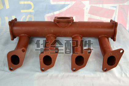
What is a generator intake manifold and what is its function?
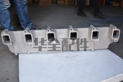
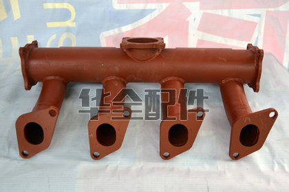
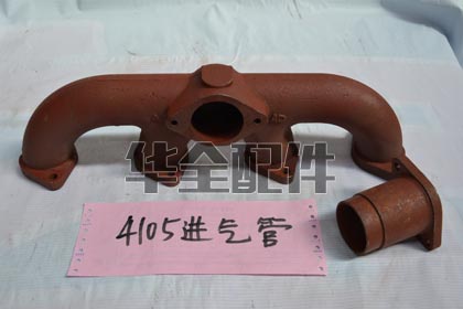
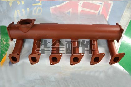
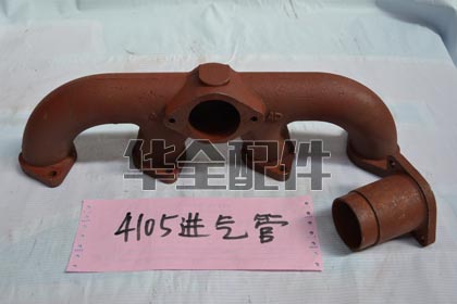
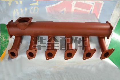
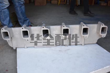
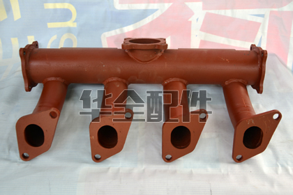
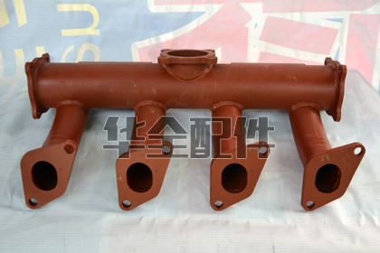
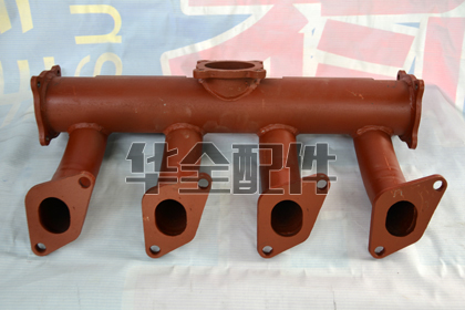
The intake manifold distributes clean, filtered air from the air cleaner/turbocharger to each cylinder's intake port(s). Its design directly influences: (1) Airflow distribution — the manifold geometry must deliver equal mass airflow to each cylinder (+-3% cylinder-to-cylinder variation) for balanced combustion and equal power output; (2) Volumetric efficiency — the manifold's runner length, cross-sectional area, and plenum volume are tuned to maximize the mass of air captured in the cylinder during the intake stroke (typical 85-95% volumetric efficiency for turbocharged diesels); (3) Turbocharger boost pressure delivery — intake manifold gauge pressure for turbocharged diesels is typically 0.5-2.5 bar above atmospheric (boost); (4) Charge air temperature — the manifold material and design affect how much heat the compressed (and thus heated) charge air loses before entering the cylinder. On a turbocharged diesel, the intake manifold operates under positive pressure and must be pressure-tested to withstand 3-4 bar for structural integrity.
What materials are generator intake manifolds made from?
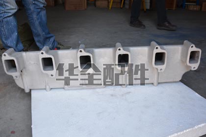
Intake manifolds are manufactured from: (1) Cast aluminum (A356/A380) — the dominant material for generator engines. Lightweight (one-third the weight of cast iron), excellent thermal conductivity (dissipates heat from the charge air), corrosion-resistant, and can be cast into complex internal geometries with smooth runner transitions; (2) Cast iron — used on older engines and large industrial platforms. Heavier but extremely rigid, the higher mass dampens intake pressure pulsations. Disadvantage: retains heat, pre-heating the intake charge (bad for volumetric efficiency); (3) Fiber-reinforced plastic/composite — emerging material for smaller engines (under 200kW). Lightest weight, inherently smooth internal surfaces, and thermally insulates the charge air from engine heat. Not rated for sustained temperatures above 150 degrees C. HUAQUAN manifolds are precision-cast aluminum with T6 heat treatment for strength and machined to 0.05mm flatness on cylinder head mounting flanges.
What are the symptoms of an intake manifold air leak?
Intake leak symptoms on turbocharged diesels: (1) Whistling or hissing noise under boost — the most obvious indicator; (2) Black smoke — the engine receives less air than the ECU believes (MAF/MAP sensors measure pre-leak airflow), so fuel is injected for a higher air mass than actually reaches the cylinders — incomplete combustion produces soot; (3) Reduced power — the engine cannot achieve rated output because oxygen is insufficient for rated fuel delivery; (4) Turbo overspeed — a leak on the pressure side means exhaust energy is still spinning the turbine at the same speed, but the compressor is pumping air into the atmosphere — the turbo can overspeed and sustain turbine wheel damage; (5) High exhaust gas temperature (EGT) — the fuel-air mixture is richer than normal, raising combustion temperature; (6) Check engine light with codes for 'boost pressure deviation' or 'air system leak'. A leak that develops suddenly indicates a ruptured hose or a blown-off hose — a major air leak that may prevent the engine from carrying load.
Which engine brands are HUAQUAN intake manifolds compatible with?
HUAQUAN intake manifolds are manufactured for: Cummins (4BT, 6BT, 6CT, ISB, ISC, ISL, QSB, QSL, NT855, KTA19/38/50, QSK), Perkins (1103-4008), Deutz (912-2015), Weichai (WD615, WD618, WP10/12/13/17, 226B, 6160-6200), Yuchai (YC4, YC6, YCK), Shangchai (SC4H-SC33W), and all Chinese diesel platforms. Each manifold is pressure-tested to 4 bar, faced to 0.05mm flatness on mounting flanges, and supplied with the correct gaskets and mounting studs/nuts. Also available: intake manifold gasket sets (MLS or composite graphite-coated steel) and mounting hardware kits.
What is intake manifold runner tuning?
Runner tuning exploits pressure wave dynamics to increase the mass of air captured (volumetric efficiency) at a specific engine speed. During the intake stroke, the descending piston creates a negative-pressure wave that travels up the intake runner at the speed of sound. When this wave reaches the open end (the plenum), it reflects as a positive-pressure wave and travels back toward the valve. If the runner length is tuned so the positive wave arrives just as the intake valve is closing, it 'rams' additional air into the cylinder. The optimum runner length for a 1,500 RPM generator engine (singe intake event per 4-stroke cycle at ~12.5 Hz per cylinder) is approximately 600-800mm — which is why generator intake manifolds physically have long runners. Variable-length manifolds that adjust runner length for different RPMs are unnecessary on constant-speed generator engines.
How should intake manifold gaskets be installed?
Proper gasket installation: (1) Verify the cylinder head intake flange is absolutely clean — any old gasket material remaining creates a leak path; (2) Check flange flatness with a straightedge — maximum 0.10mm deviation; (3) For MLS gaskets: install dry — no sealant required because the viton/polymer coating provides the seal; (4) For composite gaskets: follow manufacturer recommendation — some require a thin film of sealant on one side; (5) Start all manifold bolts/nuts hand-tight; (6) Tighten from the center outward in a spiral pattern in 2-3 torque increments; (7) Final torque typically 25-40 Nm for medium diesel engines — verify with the engine service manual; (8) After the engine has been run to operating temperature and cooled, re-torque manifold bolts (many intake gaskets require this). An intake gasket leak at one cylinder creates a lean condition for that cylinder, causing uneven running and potential exhaust valve burning.
What causes intake manifold cracking?
Causes: (1) Vibration fatigue — the manifold is cantilevered off the cylinder head and vibrates at engine frequency; stress concentrates at bolt bosses and mounting flanges; (2) Over-tightening bolts — exceeding torque specification can crack the aluminum casting at thin-walled sections; (3) Thermal cycling — repeated expansion and contraction from -40 degrees C cold start to 120+ degrees C under boost; (4) Water ingestion — if the air filter fails or rainwater enters the intake, water in the intake stroke can hydraulic-lock and crack the manifold; (5) Backfire — rare in diesels, but a severe turbocharger compressor surge can generate reverse pressure waves exceeding the manifold's design pressure; (6) Improper support — a heavy component bolted to the manifold (boost sensor, EGR valve) without adequate bracket support. Cracked aluminum manifolds can often be TIG-welded by a qualified welder — preheat to 150-200 degrees C, weld with 4043 or 5356 filler rod, and pressure-test after repair.
What is the function of the intake manifold pressure sensor (MAP sensor)?
The Manifold Absolute Pressure (MAP) sensor measures the absolute pressure (atmospheric + boost) inside the intake manifold and provides this data to the engine ECU. The ECU uses MAP readings to: (1) Calculate the mass of air entering each cylinder (along with intake air temperature and engine speed); (2) Determine the correct fuel quantity for the desired air-fuel ratio — without MAP data, the ECU cannot meter fuel correctly and defaults to a limp-mode fuel map; (3) Detect over-boost conditions and trigger protective fuel limiting; (4) Diagnose intake system leaks (unexpected low MAP) or turbocharger wastegate failure (unexpected high MAP). Common failure modes: sensor contamination from oil mist (from the crankcase ventilation system) coating the sensing element, electrical connector corrosion, or sensor diaphragm fatigue. A failed MAP sensor typically triggers a check engine light and limits engine power to 50-70%.
How do I clean a generator intake manifold?
Cleaning procedure for cast aluminum intake manifolds: (1) Remove the manifold from the engine; (2) Block all ports and openings; (3) Soak in a heated aqueous parts washer with aluminum-safe degreaser (pH 9-10.5 maximum — strong alkaline cleaners etch aluminum); (4) For carbon deposits (from EGR or crankcase ventilation), use aluminum-safe carbon remover and let soak for 2-4 hours; (5) Flush thoroughly with hot water — all cleaning chemical residue must be removed; (6) Blow dry with compressed air (regulated to 3-4 bar to prevent manifold distortion); (7) Inspect all internal passages with a borescope — ensure no debris remains; (8) If the manifold interior has oil coking from blow-by, consider installing an oil catch can in the crankcase ventilation line to prevent recurrence. Never use a torch or oven to burn out carbon deposits — this can warp the aluminum casting.
What is charge air cooling and how does it relate to the intake manifold?
Charge air cooling (intercooling/aftercooling) is the process of cooling the compressed intake air between the turbocharger compressor outlet and the intake manifold inlet. The turbocharger compresses air, which heats it — at 2 bar boost, the air temperature can reach 150-200 degrees C. Cooling this air before it enters the cylinders provides: 15-20% more air mass (density) in the same cylinder volume for increased power, lower combustion temperatures reducing NOx emissions, and reduced thermal stress on pistons and cylinder head. The charge air cooler (CAC) is typically mounted between the turbocharger and the intake manifold. The manifold itself contributes to cooling by conducting heat from the charge air into the cooler ambient air flowing through the engine compartment. A leaking CAC or a missing CAC coupling boot between the cooler and the manifold causes the same symptoms as a direct manifold leak.